
Touch and proximity sensitive display panel, display device and touch and proximity sensing method using the same

a display panel and proximity sensor technology, applied in the field of display panels, can solve the problems of increased manufacturing cost, increased thickness tb>1/b> of the entire display device, and easy noise, so as to reduce manufacturing cost and power consumption, and reduce the thickness of the display device.

Inactive Publication Date: 2011-02-03
ATLAB INC
View PDF12 Cites 170 Cited by
  • Summary
  • Abstract
  • Description
  • Claims
  • Application Information

AI Technical Summary

Benefits of technology

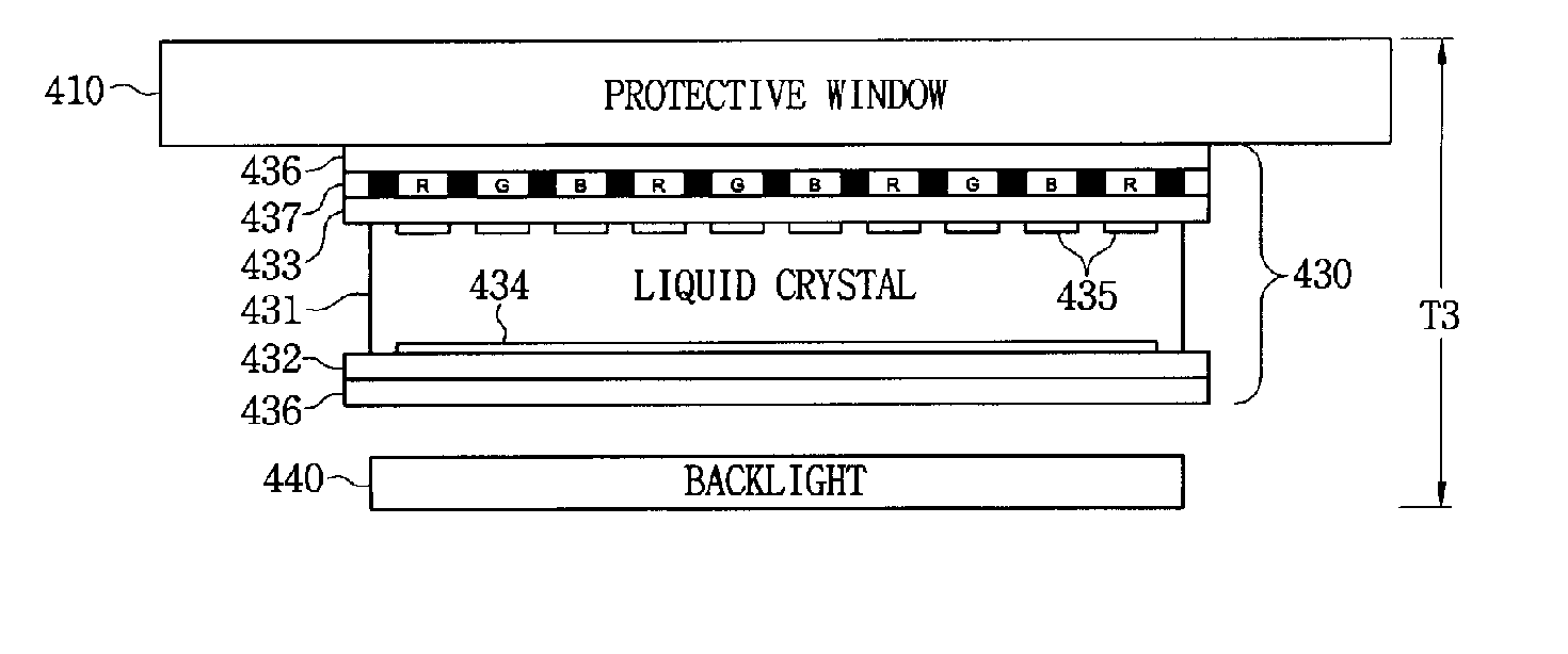
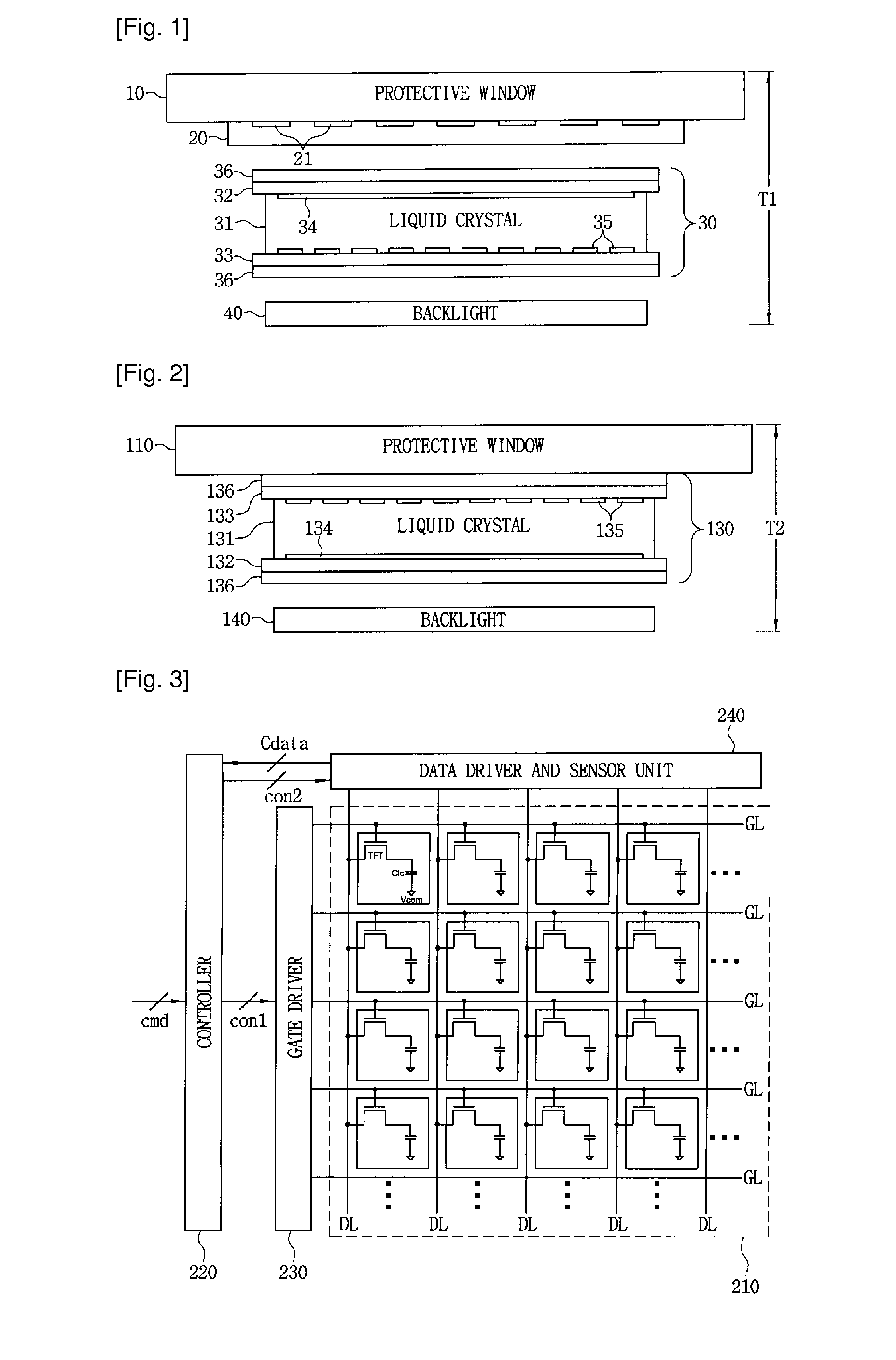
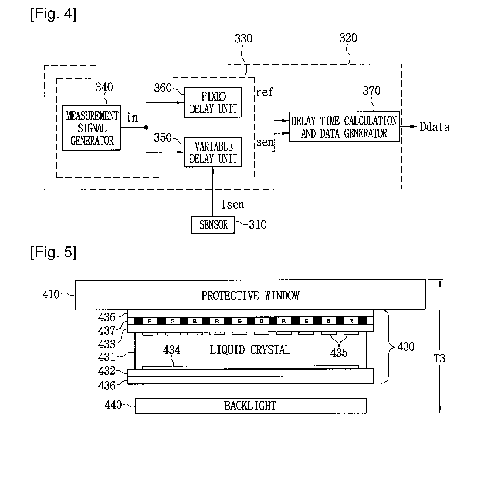
[0030]In a touch and proximity sensitive display panel, a display device, and a touch and proximity sensing method using the same according to the present invention, pixel electrodes of the display panel are used as a sensing electrode of a touch screen, such that the display panel can sense a touch and proximity of a touch object. The thickness of the display device can be significantly reduced by omitting an additional touch screen. Since the pixel electrodes are used as the sensing electrode, the touch and proximity sensing resolution can be identical with the resolution of the display panel. Various resolutions desired by a user and touch regions can be freely set. A multi-touch operation can be sensed. Manufacturing cost and power consumption can be reduced.

Problems solved by technology

Since various signals for controlling the display panel 30 are applied thereto, noise may easily occur.
In particular, there is a problem in that the thickness T1 of the entire display device increases due to the thickness of the touch screen 20 caused by the spacing inserted between the touch screen 20 and the display panel 30.
Manufacturing cost increases by separately manufacturing the touch screen of the display device and an existing touch screen does not provide a multi-touch function.

Method used


Image

  • Touch and proximity sensitive display panel, display device and touch and proximity sensing method using the same
  • Touch and proximity sensitive display panel, display device and touch and proximity sensing method using the same
  • Touch and proximity sensitive display panel, display device and touch and proximity sensing method using the same

Examples


Embodiment Construction

[0037]Hereinafter, a touch and proximity sensitive display panel, a display device, and a touch and proximity sensing method using the same will be described with reference to the accompanying drawings.

[0038]With the extension of a use field of various sensors, efforts for improving a sensing function of a sensor are being continued. As compared with the conventional sensors, new sensors have significantly improved sensing capability. And a technique for eliminating an offset or noise from a sensor has significantly developed. According to this trend, the technology of touch sensors has significantly developed.

[0039]A display device of the present invention different from the display device shown in FIG. 1 has a display panel capable of directly sensing a touch and proximity without a touch screen separated from the display panel.

[0040]FIG. 2 shows an example of a display device equipped with a touch and proximity sensitive display panel according to the present invention.

[0041]A pr...


PUM


Abstract

A touch and proximity sensitive display panel, a display device, and a touch and proximity sensing method using the same are disclosed. The display panel includes a plurality of pixels arranged in a matrix form, a pixel substrate having a pixel electrode arranged in an image output direction, a common substrate having a common electrode arranged at a position facing the pixels, and a panel controller that identifies touch and proximity positions of a touch object by sensing electrostatic capacitances of the pixel electrodes through the data lines in a touch-sensing mode. The display panel can sense the touch and proximity of the touch object without an additional touch screen.

Description

TECHNICAL FIELD[0001]The present invention relates to a display panel, and more particularly, to a touch and proximity sensitive display panel, a display device, and a touch and proximity sensing method using the same.BACKGROUND ART[0002]A touch screen, which is a representative device of devices capable of sensing a touch or proximity, is an input means available in place of a mouse or keyboard. Information may be directly input on a display screen of the touch screen using a finger or stylus. Accordingly, the touch screen is advantageous in that anyone may easily perform an input operation since an input method is intuitive, and is evaluated as an ideal input mean in a graphical user interface (GUI) application. At present, the touch screen is widely used in various fields such as mobile phones, personal digital assistants (PDAs), terminals installed in banks or public offices, medical appliances, and guide display devices. Recently, the demands of touch screens are increasing wit...

Claims


Application Information

Patent Timeline
IPC IPC(8): G06F3/041H05B44/00
CPCG02F1/13338G06F1/3203Y02B60/32G06F3/0412G06F3/044G06F1/3262G06F3/0443Y02D30/50G06F3/04166G06F3/0442G06F1/3265H10K59/40
Inventor LEE, BANG-WON
Owner ATLAB INC
Learn More