
Fuel system control

a fuel system and fuel technology, applied in electrical control, machines/engines, mechanical equipment, etc., can solve the problems of reducing affecting so as to reduce the fluidity of the fuel

Active Publication Date: 2011-02-03
FORD GLOBAL TECH LLC
View PDF33 Cites 29 Cited by
  • Summary
  • Abstract
  • Description
  • Claims
  • Application Information

AI Technical Summary

Benefits of technology

[0002]Vehicle engines may be configured to operate using diesel fuels. However, at low ambient temperatures, such as during an engine cold-start, wax may precipitate out of the diesel fuel. The precipitated wax may clog a fuel filter while also reducing the fluidity of the fuel. The amount of wax that precipitates from the fuel may depend upon the fuel properties and ambient temperature the vehicle is started in. As such, the precipitated wax in the fuel reduces the pressure of the low pressure fuel system and performance of the high pressure fuel system and, if severe enough, can cause damage to the fuel system.
[0007]In one example, the operation of the supply pump in a vehicle fuel system may be adjusted responsive to both a temperature and pressure of the fuel. Herein, at the onset of an engine cold-start and during engine operation in cold ambient conditions, the supply pump may be operated in the more power-intensive pressure-controlled mode for an interval to rapidly raise the fuel temperature to a first threshold temperature and pressure. Once the threshold temperature and pressure have been attained, the supply pump operation may be switched to the more energy-efficient volume-controlled mode. By operating the supply pump responsive to both a temperature and pressure of the fuel, substantial fuel economy benefits may be achieved. For example, the combination of a higher pressure threshold and a lower temperature threshold may suffice to enable improved wax removal and increased fuel fluidity. In some examples, the higher pressure and lower temperature combination may entail a shorter pump operation, thereby reducing the fuel consumption of the vehicle.
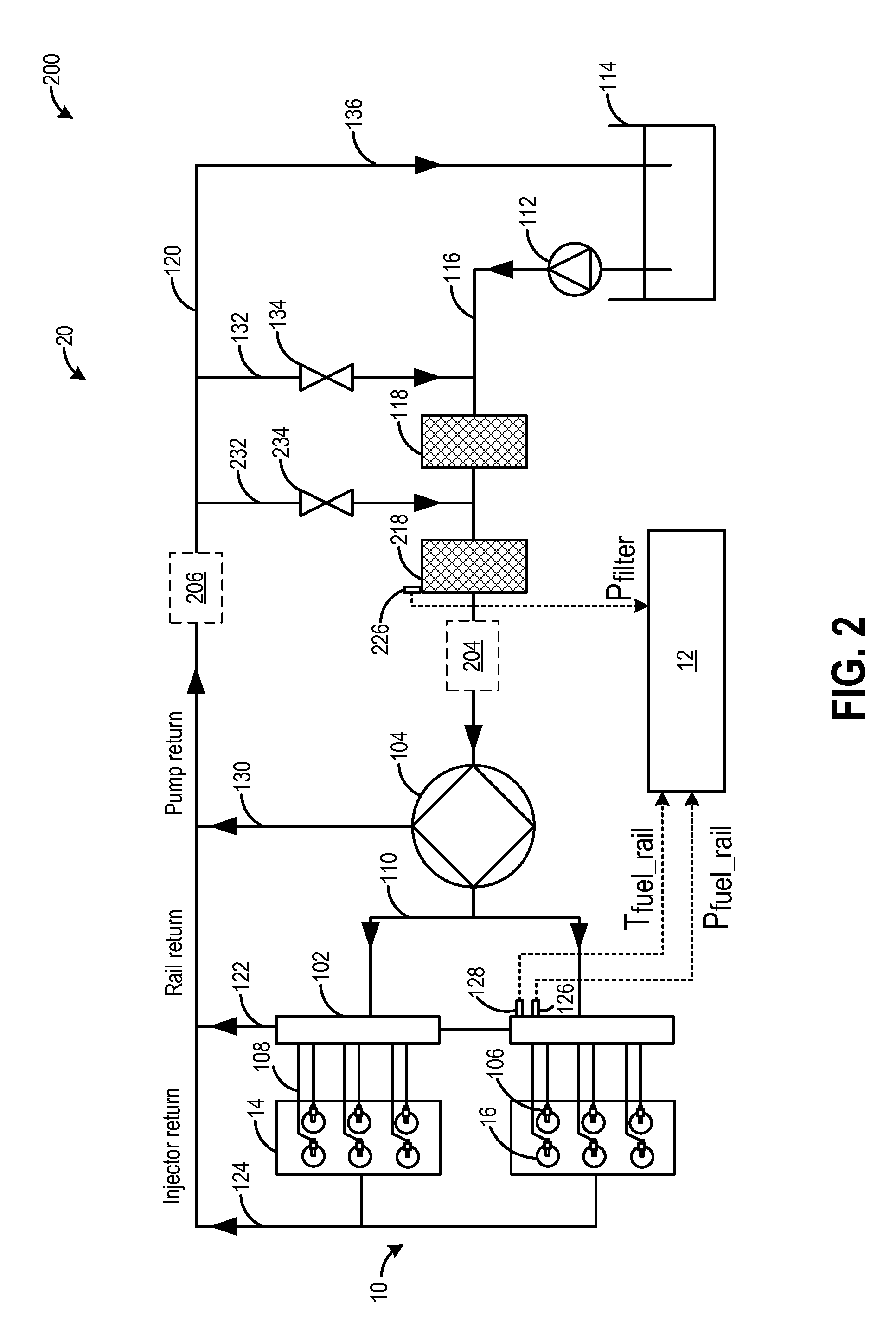
[0008]Further improvements in fuel fluidity and wax removal may be achieved by recirculating at least some of the fuel pressurized and heated through the supply pump into the inlet of one or more system fuel filters along respective recirculation passages. Flow through the recirculation passages may be regulated by respective one or more thermal recirculation valves. As such, the heated return fuel may be re-circulated irrespective of the operating mode of the supply pump. The amount of return fuel re-circulated through the fuel filters may also be adjusted responsive to the fuel temperature and / or pressure by regulating the flow of return fuel through the thermal recirculation valves. During operation of the pump in the volume-controlled mode, the build-up and removal of wax at the fuel filter may be diagnosed by analyzing the pressure at the filter outlet. By adjusting the recirculation flow based on a fuel temperature and / or pressure, wax removal may be expedited and the quality of fuel injection may be improved. Furthermore, by diagnosing and distinguishing filter clogging due to wax build-up from filter clogging due to extraneous matter (i.e. contaminants such as dust), the quality of engine and pump operation may be improved.

Problems solved by technology

However, at low ambient temperatures, such as during an engine cold-start, wax may precipitate out of the diesel fuel.
The precipitated wax may clog a fuel filter while also reducing the fluidity of the fuel.
As such, the precipitated wax in the fuel reduces the pressure of the low pressure fuel system and performance of the high pressure fuel system and, if severe enough, can cause damage to the fuel system.
However, the inventors have recognized several potential issues with such approaches.
Specifically, when adjusting the supply pump operation mode responsive to fuel temperature, if the temperature is set low (for example, to improve fuel economy), there may be insufficient wax removal during some conditions.
Alternatively, if the temperature is set higher (to ensure sufficient wax removal), under some conditions this may prolong the high work load of the pump more than necessary, adversely impacting fuel economy.
Thus, continuing high work loading of the pump may be unnecessary.
Further still, variations in the fuel quality and properties may significantly affect how much, and at what temperatures, wax is formed or removed.

Method used


Image

  • Fuel system control
  • Fuel system control
  • Fuel system control

Examples


Embodiment Construction

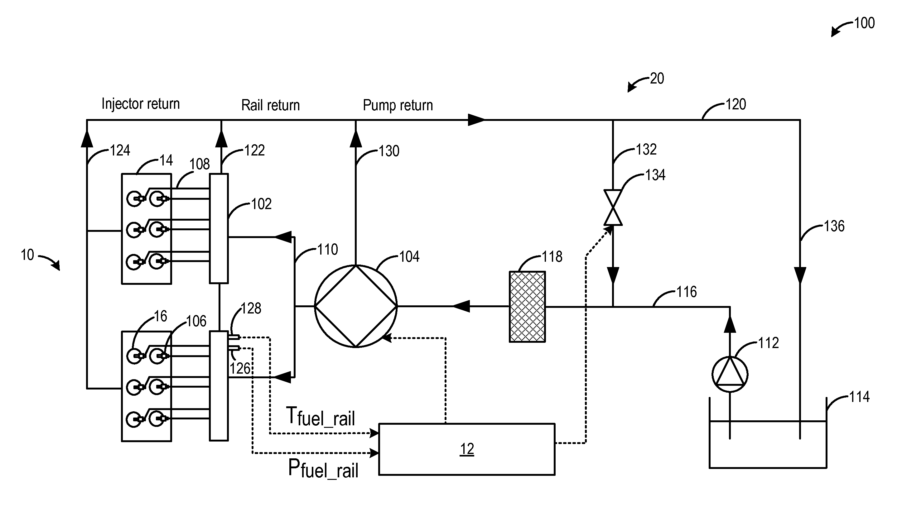
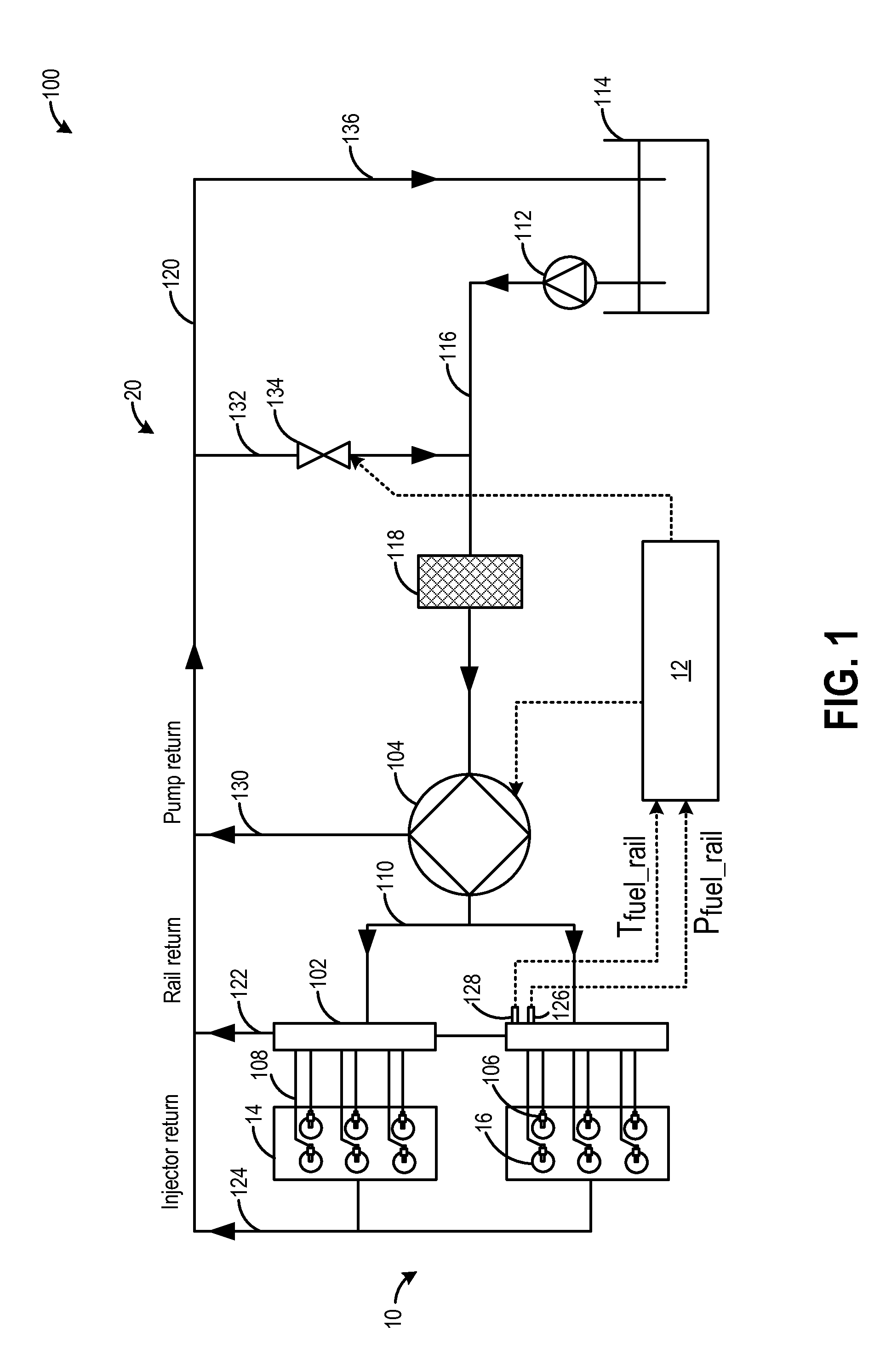
[0014]The following description relates to systems and methods for operating a fuel system in a diesel-fuelled engine. As depicted in FIGS. 1-2, the fuel system may be configured with one or more recirculation valves for recirculating heated return fuel through one or more fuel filters. By recirculating diesel fuel that has been heated following pressurization and discharge from a supply fuel pump, wax removal may be expedited. An engine controller may be configured to adjust the operation of the supply pump at least between a more power-intensive pressure-controlled mode and a more energy-efficient volume-controlled mode responsive to both a fuel temperature and pressure, by performing a control routine, such as the routine depicted in FIG. 3, during engine cold-starts. The engine controller may further adjust fuel recirculation through the fuel filters responsive to the fuel temperature and / or pressure. By adjusting fuel pump operation responsive to a fuel temperature and pressure...


PUM


Abstract

Methods and systems are provided for operating a fuel system in an engine, the fuel system including a supply pump for delivering fuel to the fuel system and pressurizing fuel received from a feed pump, a fuel tank, a fuel filter for filtering fuel, a fuel rail, and a fuel injector. One example method comprises, during an engine cold-start, operating the supply pump, and adjusting a supply pump operation mode between at least a pressure-controlled mode and a volume-controlled mode based on a fuel temperature and pressure.

Description

FIELD [0001]The present application relates to methods and systems for controlling the fuel system of a diesel engine, specifically during a start and engine operation after start in cold ambient conditions.BACKGROUND AND SUMMARY [0002]Vehicle engines may be configured to operate using diesel fuels. However, at low ambient temperatures, such as during an engine cold-start, wax may precipitate out of the diesel fuel. The precipitated wax may clog a fuel filter while also reducing the fluidity of the fuel. The amount of wax that precipitates from the fuel may depend upon the fuel properties and ambient temperature the vehicle is started in. As such, the precipitated wax in the fuel reduces the pressure of the low pressure fuel system and performance of the high pressure fuel system and, if severe enough, can cause damage to the fuel system.[0003]Various strategies may be used to reduce and remove the precipitation of wax from diesel fuels. In one example approach, the mode of operatio...

Claims


Application Information

Patent Timeline
Patent Type & Authority Applications(United States)
IPC IPC(8): F02D41/38
CPCF02D41/3845F02D2200/0602F02M63/0225F02D2250/31F02M53/00F02D2200/0606
Inventor CHAMARTHI, GOPAL KRISHNAFULTON, BRIEN LLOYDOBERSKI, CHRISTOPHERLYON, PETER MITCHELL
Owner FORD GLOBAL TECH LLC
Learn More