Apparatus and methods for transferring an implanted elongate body to a remote site

Inactive Publication Date: 2011-01-27
PACESETTER INC
View PDF18 Cites 92 Cited by
  • Summary
  • Abstract
  • Description
  • Claims
  • Application Information

AI Technical Summary

Benefits of technology

[0005]In one embodiment, a method for transferring an implanted medical component (such as a guidewire) from an initial insertion site of the vasculature to an exit site of the vasculature in a patient with pre-existing implanted device, such as a pacemaker, defibrillator or diagnostic sensor system, is provided. In one embodiment, a guidewire is inserted into the vasculature at an insertion site and externalized at a separate exit site of the vasculature. Guidewire insertion is performed using a protective barrier (such as a sheath) having one or more ports or lumena to, for example, reduce the risk of entanglement with the pre-existing implanted device.
[0038]In another embodiment, another guidewire with adjustable flexibility is provided. This guidewire comprises an elongate flexible tubular body having a proximal end and a distal end, a central lumen extending distally into the tubular body from the proximal end, and an elongate flexible core wire axially moveable within the central lumen. Axial proximal retraction of the core wire with respect to the tubular body increases the flexibility of at least a portion of the guidewire, and axial distal advance of the core wire with respect to the tubular body decreases the flexibility of at least a portion of the guidewire. The length of the elongate flexible tubular body is at least about 180 cm. In some embodiments, the portions of the guidewire capable of changes in flexibility define a flexibility zone of the guidewire. In some embodiments, the flexibility zone comprises at least about the proximal 90% length of the elongate tubular body. In other embodiments, the flexibility zone comprises generally the entire length of the elongate tubular body.
[0040]In still another embodiment, a method of accessing a target site is provided. In one embodiment, this method comprises introducing a guidewire into a patient through an introduction site, the guidewire having a first, reduced flexibility, externalizing at least a portion of the guidewire through a different site of the body, and adjusting the guidewire to have a second flexibility. In further embodiments, the method also comprises the step of introducing a catheter along the guidewire after adjusting the guidewire to have a second flexibility.
[0044]In one embodiment, the rotational coupling includes a housing having an atraumatic surface configured to be pulled through the patient's body from a first access point to a second access point while attached to the implanted lead without damaging tissue within the patient's body In another embodiment, the rotational coupling includes a screw configured to mate with the implanted lead. In another embodiment, the transfer guidewire assembly also includes a stylet extending from a distal end of the rotational coupling that is sized to enter the implanted lead.

Problems solved by technology

The placement of a permanently or temporarily implantable device in the left side of the heart, and particularly the left atrium, may be difficult at a particular site of insertion because an operator must contend with the anatomical obstacles or equipment limitations presented by the catheter's route to the left heart.
For example, it is more difficult to access the left atrium by performing an atrial transseptal puncture from an insertion point on the neck or near the shoulder than it is to perform a standard transfemoral Brockenbrough needle puncture of the intra-atrial septum from the right groin region.
A superior insertion site, however, provides a significantly tortuous and winding pathway to the intra-atrial septum, which makes the use of a Brockenbrough needle puncture technically more difficult from this insertion site.
For example, it can be difficult to perform mitral balloon valvuloplasty from the inferior venous approach because an abrupt curve must be made in the left atrium to reach the mitral valve.

Method used


Image

  • Apparatus and methods for transferring an implanted elongate body to a remote site
  • Apparatus and methods for transferring an implanted elongate body to a remote site
  • Apparatus and methods for transferring an implanted elongate body to a remote site

Examples


Embodiment Construction

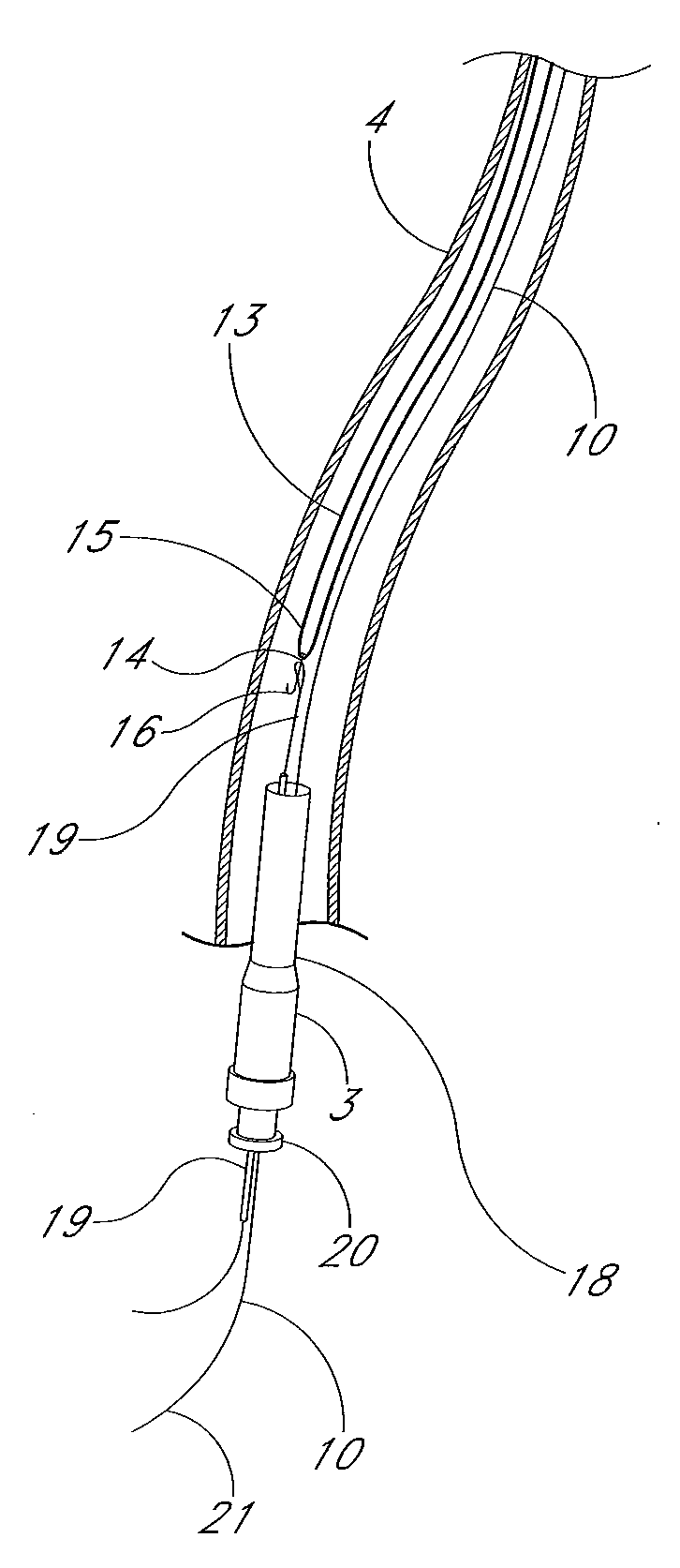
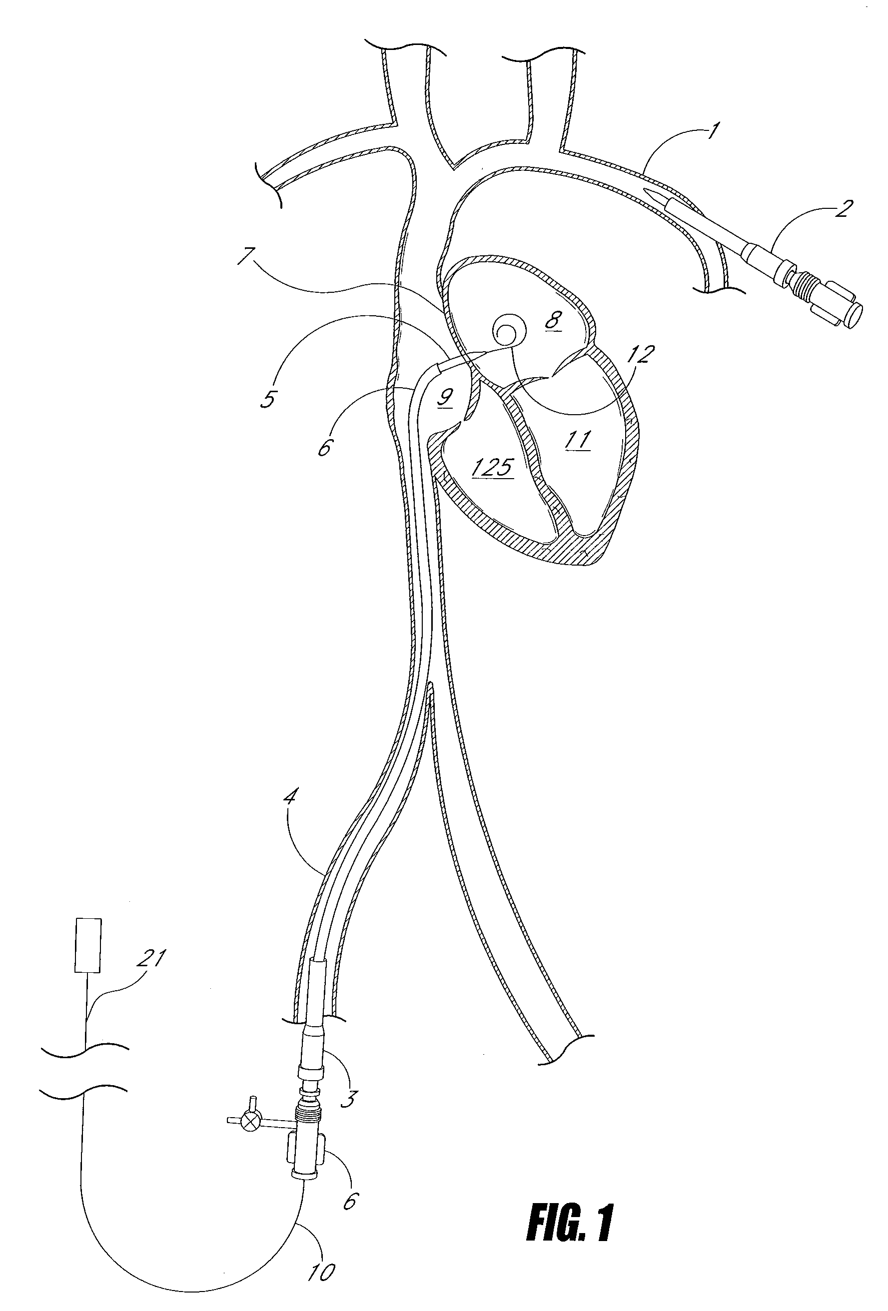
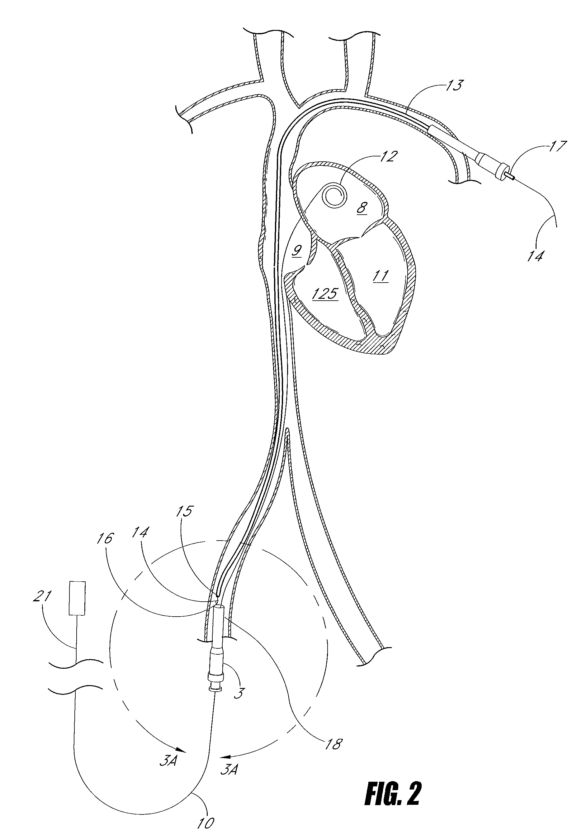
[0084]Several embodiments of the present invention generally relate to a system and method for performing catheterization of a body structure from a standard catheter insertion site, advancing a guidewire or other flexible member (e.g., an electrical lead, conduit, tube, etc.) into the body structure from that insertion site, and transferring the proximal end of the guidewire to an alternative insertion site while leaving the distal end of the guidewire within the body structure. The transferred guidewire may then be used for the placement of a second device or to perform a desired procedure from the alternative insertion site. Some embodiments relate to methods for standard transseptal puncture of the left atrium from a femoral vein, where the guidewire is then transferred from the femoral insertion site to a subclavian vein insertion site for the implantation of a left atrial pressure-monitoring device. Several embodiments described herein are also generally applicable to other si...


PUM


Abstract

A transfer guidewire assembly configured to manipulate an implanted elongate body includes a flexible elongate portion, such as a guidewire, and coupler. The flexible elongate body has a proximal end and a distal end attached to the coupler. The coupler can include a catheter and / or a handle. The handle can include a screw. The coupler is configured to be removably attached to the end of an implanted elongate body, for example, by forming an interference fit with the outside diameter of the implanted body. A method for transferring an end of an implanted medical component from first site to a second site within a patient, such as a pacemaker, defibrillator, and / or sensor lead, etc., includes inserting a guidewire into the body at the first site and externalizing the guidewire at the second site. A proximal portion of the implanted component near the first site and is attached to the guidewire. The proximal portion of the implanted component is pulled through the patient's body and out the second site with the transfer guidewire assembly.

Description

CROSS-REFERENCE TO RELATED APPLICATIONS[0001]The present application is a continuation-in-part of U.S. application Ser. No. 11 / 622,654, filed on Jan. 12, 2007, which claims priority under 35 U.S.C. §119(e) to U.S. Provisional Application No. 60 / 764,878 filed on Feb. 3, 2006, the disclosures of which are herein incorporated by reference in their entirety.FIELD OF THE INVENTION[0002]This invention generally relates to devices, systems and methods for transferring a device from a first location, such as an initial insertion site on the body, to a second location, such as a different insertion site on the body.BACKGROUND OF THE INVENTION[0003]The placement of a permanently or temporarily implantable device in the left side of the heart, and particularly the left atrium, may be difficult at a particular site of insertion because an operator must contend with the anatomical obstacles or equipment limitations presented by the catheter's route to the left heart. For example, it is more diff...

Claims


Application Information

Patent Timeline
IPC IPC(8): A61B19/00
CPCA61B17/3468A61B2017/00243A61N1/056A61M25/09A61M2025/0681A61M25/01
Inventor EIGLER, NEAL L.WHITING, JAMES S.WARDLE, JOHN L.HAFELFINGER, WERNERDIXIT, APRATIM
Owner PACESETTER INC
Why Eureka
Try Eureka