Hydraulically Driven Machine Improvement

a technology of hydraulic drive and machine drive, which is applied in the direction of reciprocating piston engines, flexible wall reciprocating engines, positive displacement liquid engines, etc., can solve the problems of frictional wear of displacement organs and the inability of the drive of the machine to be properly isolated from the pumped material, so as to achieve less complicated and reliable effects

Active Publication Date: 2011-01-27
GARNIMAN
View PDF3 Cites 3 Cited by
  • Summary
  • Abstract
  • Description
  • Claims
  • Application Information

AI Technical Summary

Benefits of technology

[0011]The above-described inventive arrangement results in eliminating or greatly reducing radial deformation of the bellows-like diaphragms resulting in greater reliability and enhanced life for the diaphragms.
[0014]By the use of this hydromechanical switch, the hydraulic machine can be operated without the need for electromagnetically actuated and electronically controlled directional valves and as a result the machine is less complicated and more reliable.

Problems solved by technology

However such displacement organs are subject to frictional wear and the drive of the machine is not properly isolated from the pumped material.

Method used


Image

  • Hydraulically Driven Machine Improvement
  • Hydraulically Driven Machine Improvement
  • Hydraulically Driven Machine Improvement

Examples


Embodiment Construction

[0023]The principal improvement of the invention relates to a plunger device to provide fluids separation and, as a subsidiary aspect to a hydromechanical switch, it being understood that these two aspects can be incorporated individually or together in a hydraulically driven pumping machine.

Plunger Separating Fluids

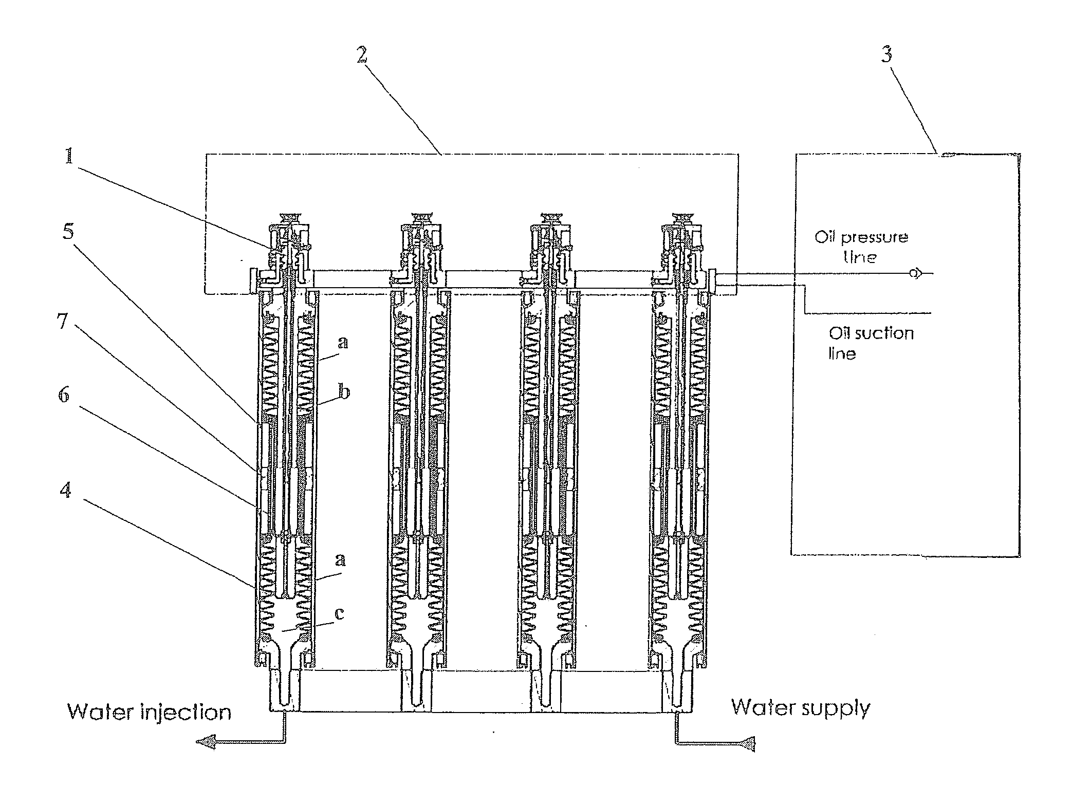
[0024]The hydraulically driven pumping machine shown in FIG. 1 comprises one or several cylinders 5, a switching control system 1 and a hydraulic drive unit 3. The machine is normally a multicylinder machine and such basic hydraulic multicylinder machine is described in detail in PCT patent application WO 2005 / 119063.

[0025]To enhance the life of the bellows-like diaphragms, namely to eliminate their radial deformation under pressure differentials arising between internal and external bellows cavities, the basic machine described in WO 2005 / 119063 was improved in the following way.

[0026]The pump's cylinder 5 contains two bellows 4 and 10 (see FIG. 2) mechanically connecte...


PUM


Abstract

A hydraulically driven diaphragm pumping machine comprises a plunger (6) that is slidably mounted in a middle part of the inside of the machine's hydraulic cylinder (5) between first and second bellow-like diaphragms (4,10). Ends of the plunger (6) are connected to the first and second bellows-like diaphragm (10) to define respective first and second outer annular spaces (a) that are independent of one another, and the pressure of fluid in the first annular space (a) is independent of the pressure of fluid in the second annular space (a). The machine may also comprise a hydromechanical switch for commutating a valve (102) to automatically control the supply of hydraulic fluid to the hydraulic cylinder at given moments of the machine's cycle.

Description

FIELD OF THE INVENTION[0001]The invention relates to hydraulically driven machines, in particular for pumping difficult-to-pump fluid materials, like minerals, ores, sludges, suspensions, slurries, and gels. These pumping machines may be referred to herein simply as pumps or machines.BACKGROUND OF THE INVENTION[0002]Conventional pumping machines that can be used for difficult-to-pump materials have displacement organs such as pistons, plungers, peristaltic hoses etc. However such displacement organs are subject to frictional wear and the drive of the machine is not properly isolated from the pumped material.[0003]WO 2005 / 119063 discloses a hydraulically driven multicylinder diaphragm pumping machine, in particular for pumping difficult-to-pump materials. This pumping machine comprises a plurality of pump cylinders each having one end with an inlet and outlet for fluid to be pumped and another end with an inlet and outlet for hydraulic fluid. These inlets and outlets can be a separat...

Claims


Application Information

Patent Timeline
Patent Type & Authority Applications(United States)
IPC IPC(8): F04B17/00
CPCF04B9/105F04B43/1136F04B43/113
Inventor EYSYMONTT, JAN
Owner GARNIMAN
Why Eureka
Try Eureka