
Video Decoding Method

Inactive Publication Date: 2011-01-27
HITACHT MAXELL LTD
View PDF5 Cites 3 Cited by
  • Summary
  • Abstract
  • Description
  • Claims
  • Application Information

AI Technical Summary

Benefits of technology

[0007]However, with such existing techniques, there is a need for additional determination information as to, of the predicted image generated by performing motion estimation between decoded images and the predicted image generated by a method similar to existing coding standards, based on which predicted image coding / decoding is to be performed, which, depending on the input image information, may in some cases cause compression efficiency to drop below those of conventional standards. The present invention is made in view of the problems mentioned above, and an aspect thereof is to further reduce coding bits in coding / decoding video.
[0009]With the present invention, it is possible to record and transmit video signals with fewer coding bits as compared to conventional schemes.

Problems solved by technology

However, with such existing techniques, there is a need for additional determination information as to, of the predicted image generated by performing motion estimation between decoded images and the predicted image generated by a method similar to existing coding standards, based on which predicted image coding / decoding is to be performed, which, depending on the input image information, may in some cases cause compression efficiency to drop below those of conventional standards.

Method used


Image

  • Video Decoding Method
  • Video Decoding Method
  • Video Decoding Method

Examples


embodiment 1

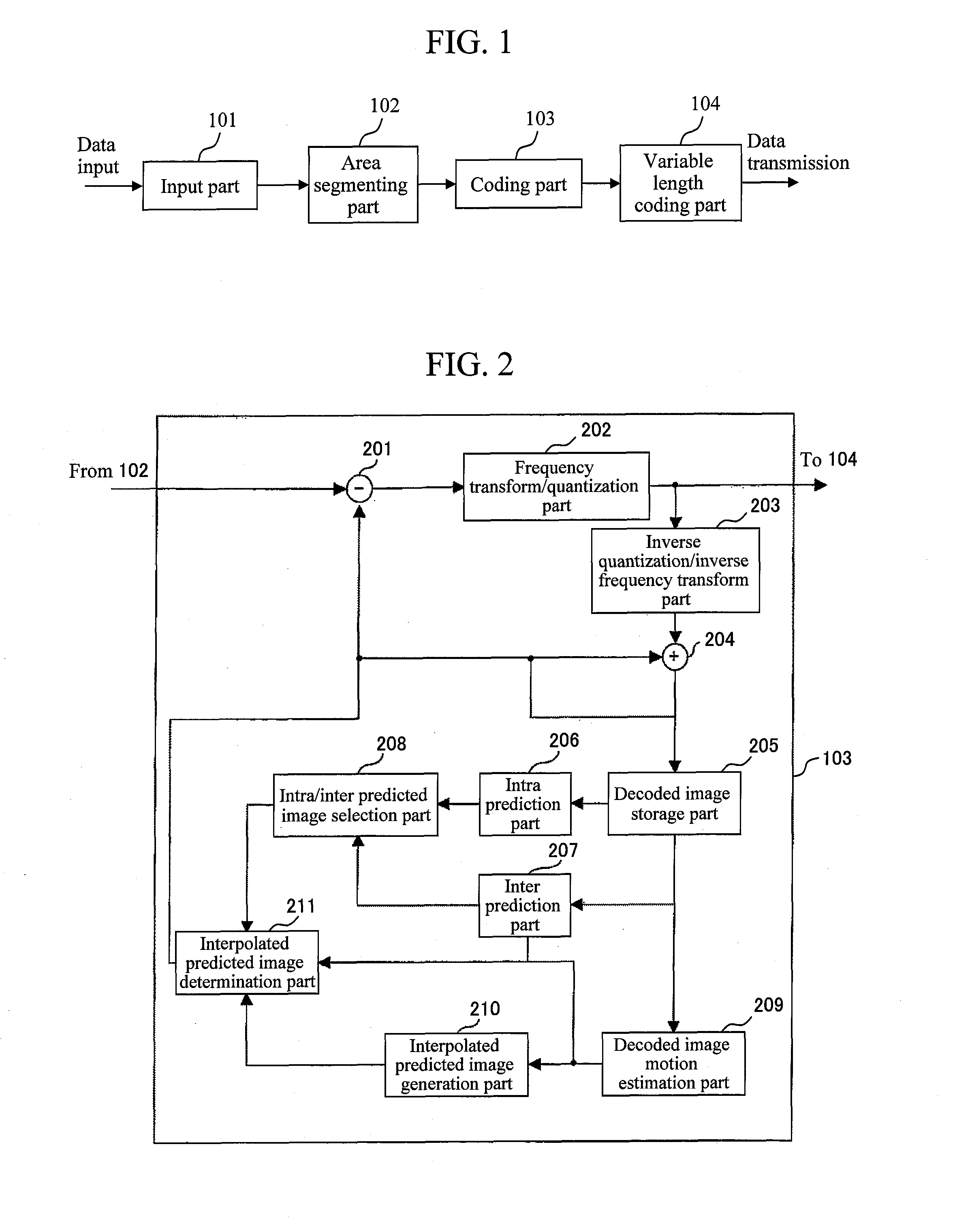
[0025]FIG. 1 shows the configuration of a video coding device according to the present embodiment.

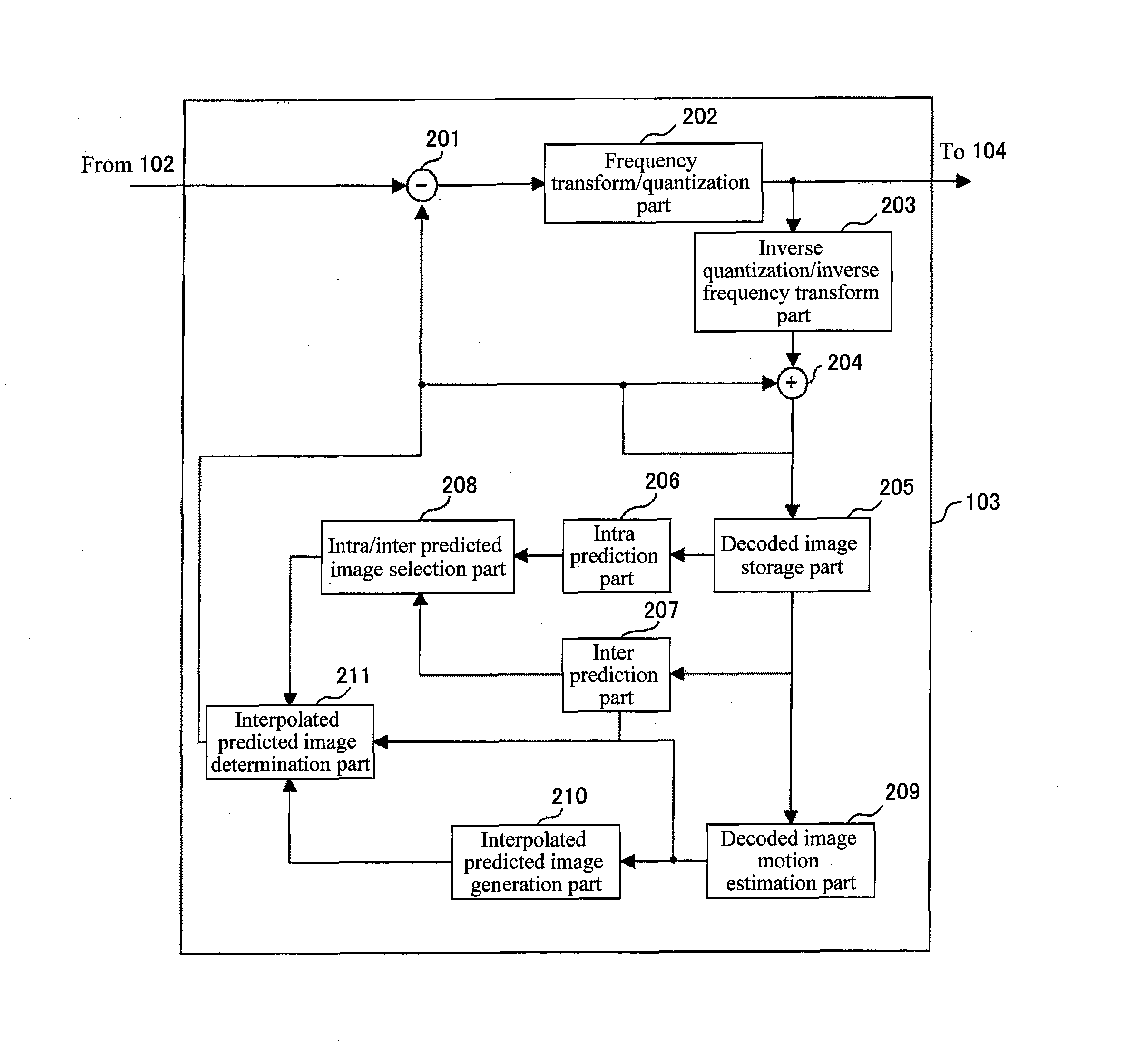
[0026]A video coding device according to the present embodiment comprises: an input part 101 to which image data is inputted; an area segmenting part 102 that segments the inputted image data into small segments; a coding part 103 that performs a coding process and a local decoding process with respect to the image data segmented at the area segmenting part 102; and a variable length coding part 104 that performs variable length coding on the image data coded at the coding part 103.

[0027]Operations of each processing part of a video coding device according to the present embodiment will be described in further detail below.

[0028]At the input part 101, the inputted image data is rearranged in the order in which coding is to be performed. This rearrangement of the order is such that depending on which of an intra predicted picture (I picture), an inter predicted picture (P picture), and a...

embodiment 2

[0068]In Embodiment 1, the determination process for the predicted image of the area to be coded / decoded was performed at the interpolated predicted image determination parts 211, 607 of the coding part 103 and the decoding part 503, using similarity degrees of motion vectors. In the present embodiment, the determination process for the predicted image of the area to be coded / decoded is performed in accordance with, in place of the similarity degrees of motion vectors, the number of areas peripheral to the area to be coded / decoded that have an interpolated predicted image.

[0069]A determination process by an interpolated predicted image determination part in a video coding device and video decoding device according to the present embodiment will be described with reference to FIG. 8. It is noted that since the structures and operations of a video coding device and video decoding device according to the present embodiment are, with the exception of the structure and operation of the i...

embodiment 3

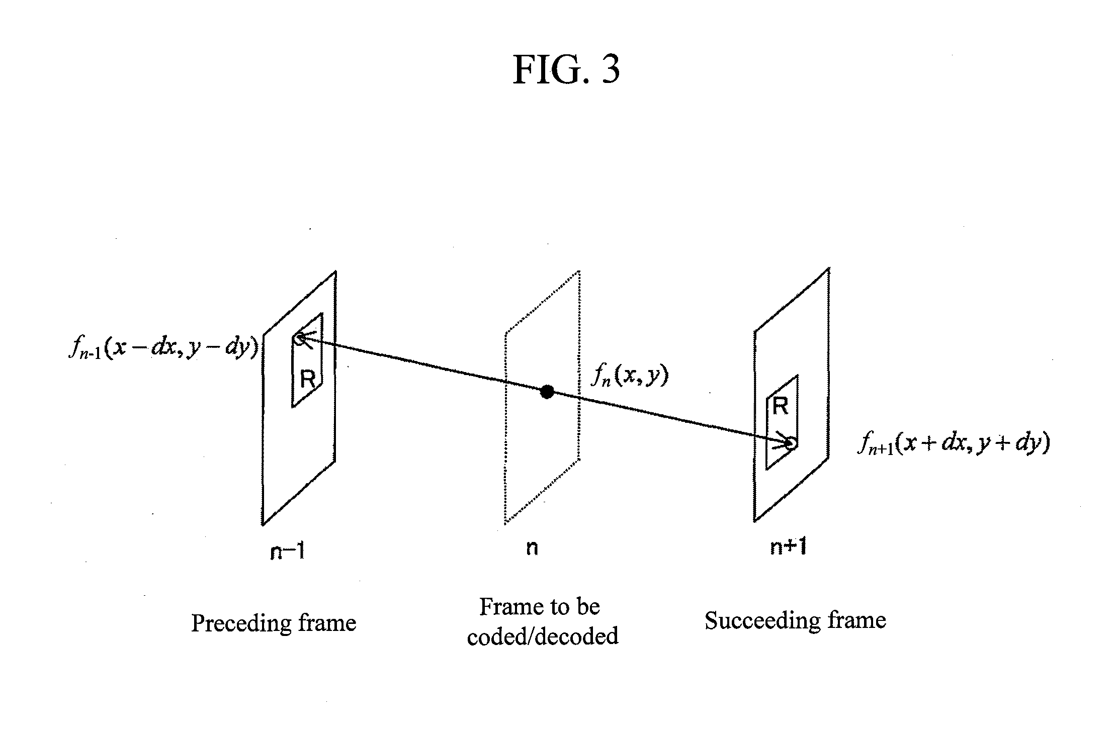
[0086]In Embodiments 1 and 2, a determination process with respect to the predicted image of the area to be coded / decoded was performed at the interpolated predicted image determination part based on the similarity degrees of the motion vectors of the areas peripheral to the area to be coded / decoded or based on the number of areas peripheral to the area to be coded / decoded that have an interpolated predicted image. In the present embodiment, a determination process with respect to the predicted image of the area to be coded / decoded is performed using coding information of an already coded / decoded frame other than the frame to be coded / decoded. More specifically, a determination process is performed using similarity degrees of motion vectors of an area within an already coded / decoded frame that is temporally distinct from the frame in which the area to be coded / decoded is present, the area (hereinafter referred to as an anchor area) being located at the same coordinates as the area t...


PUM


Abstract

In methods in which coding is performed by switching, per area, between a predicted image generated by an existing coding standard and an image newly generated by performing motion estimation between decoded images, it is necessary to further provide determination information as to which image is to be used, which may in some cases result in compression efficiency that is inferior to those of conventional standards depending on the input video. By determining whether a predicted image generated by an existing coding standard is to be used or an image newly generated by performing motion estimation between decoded images is to be used based on coding information within the frame to be coded or within a previously coded frame, the need for such determination information is obviated to improve compression efficiency.

Description

CLAIM OF PRIORITY[0001]The present application claims priority from Japanese patent application JP 2009-172670 filed on Jul. 24, 2009, the content of which is hereby incorporated by reference into this application.BACKGROUND OF THE INVENTION[0002]1. Field of the Invention[0003]The present invention relates to a video coding technique for coding video and to a video decoding technique for decoding video.[0004]2. Background Art[0005]As techniques in the field, such international coding standards as MPEG (Moving Picture Experts Group) and the like have conventionally been known. There is also known a technique in which compression efficiency is improved by concurrently using, in order to further reduce image data, a predicted image generated by performing motion estimation between decoded images as well as a predicted image generated by a method similar to existing coding techniques (Patent Document 1).[0006][Patent Document 1] JP Patent Publication (Kokai) No. 2008-154015 ASUMMARY OF ...

Claims


Application Information

Patent Timeline
IPC IPC(8): H04N7/32H04N19/105H04N19/50H04N19/139H04N19/176H04N19/196H04N19/423H04N19/503H04N19/51H04N19/513H04N19/593H04N19/60H04N19/61H04N19/91
CPCH04N19/139H04N19/159H04N19/44H04N19/61H04N19/12H04N19/176
Inventor SAITO, SHOHEIMURAKAMI, TOMOKAZU
Owner HITACHT MAXELL LTD
Learn More