
Security system with power saving feature and method thereof

a technology of security system and power saving feature, which is applied in the field of security system, can solve the problems of not meeting the requirement of prompt response to the triggering event, the performance of the power consumption of the conventional security system is a lot to be desired, and the current continuously consumes hundreds of milliamperes (ma) for the electromagnetic lock

Inactive Publication Date: 2011-01-27
LAI CHIN LUN +3
View PDF4 Cites 27 Cited by
  • Summary
  • Abstract
  • Description
  • Claims
  • Application Information

AI Technical Summary

Benefits of technology

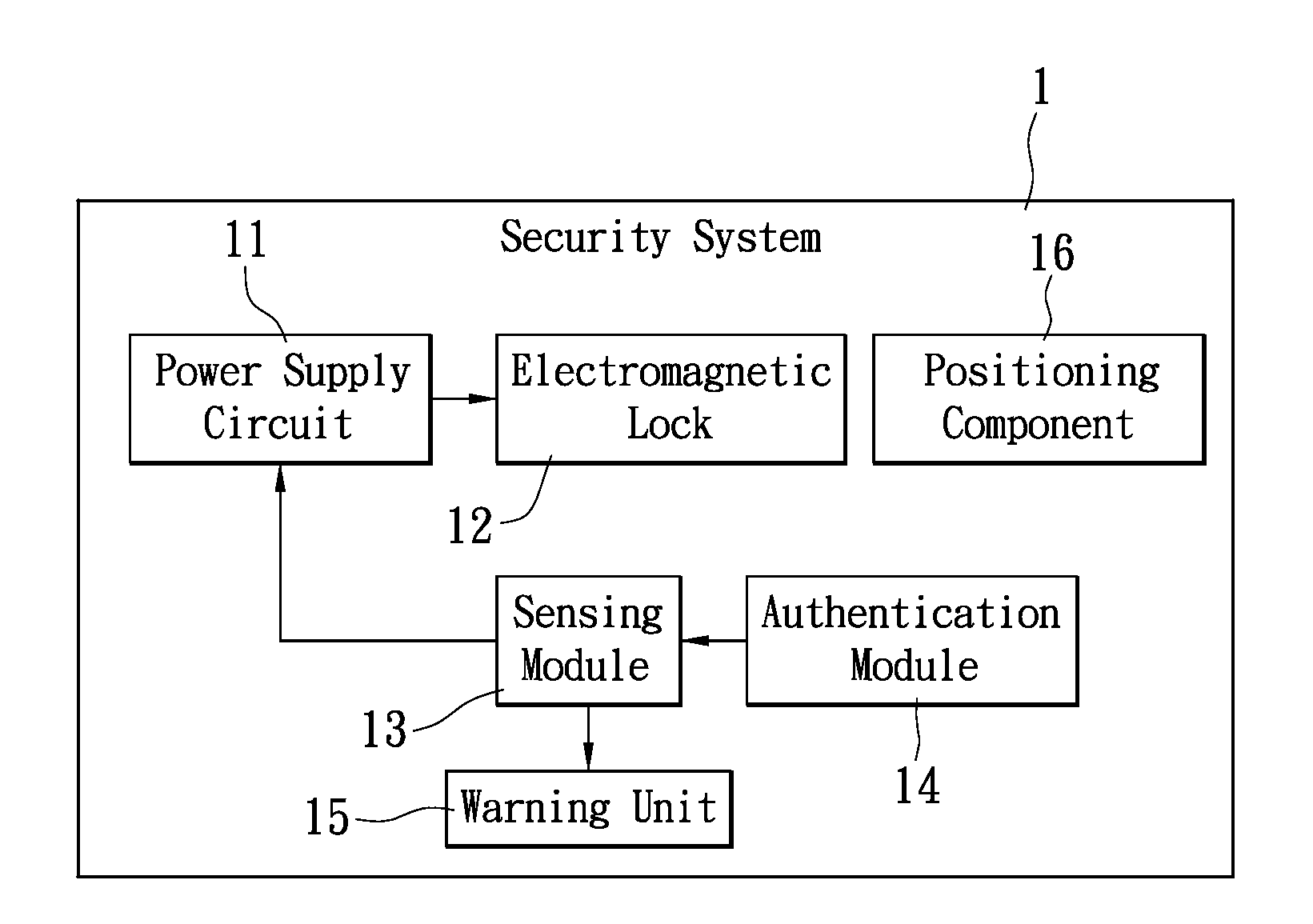
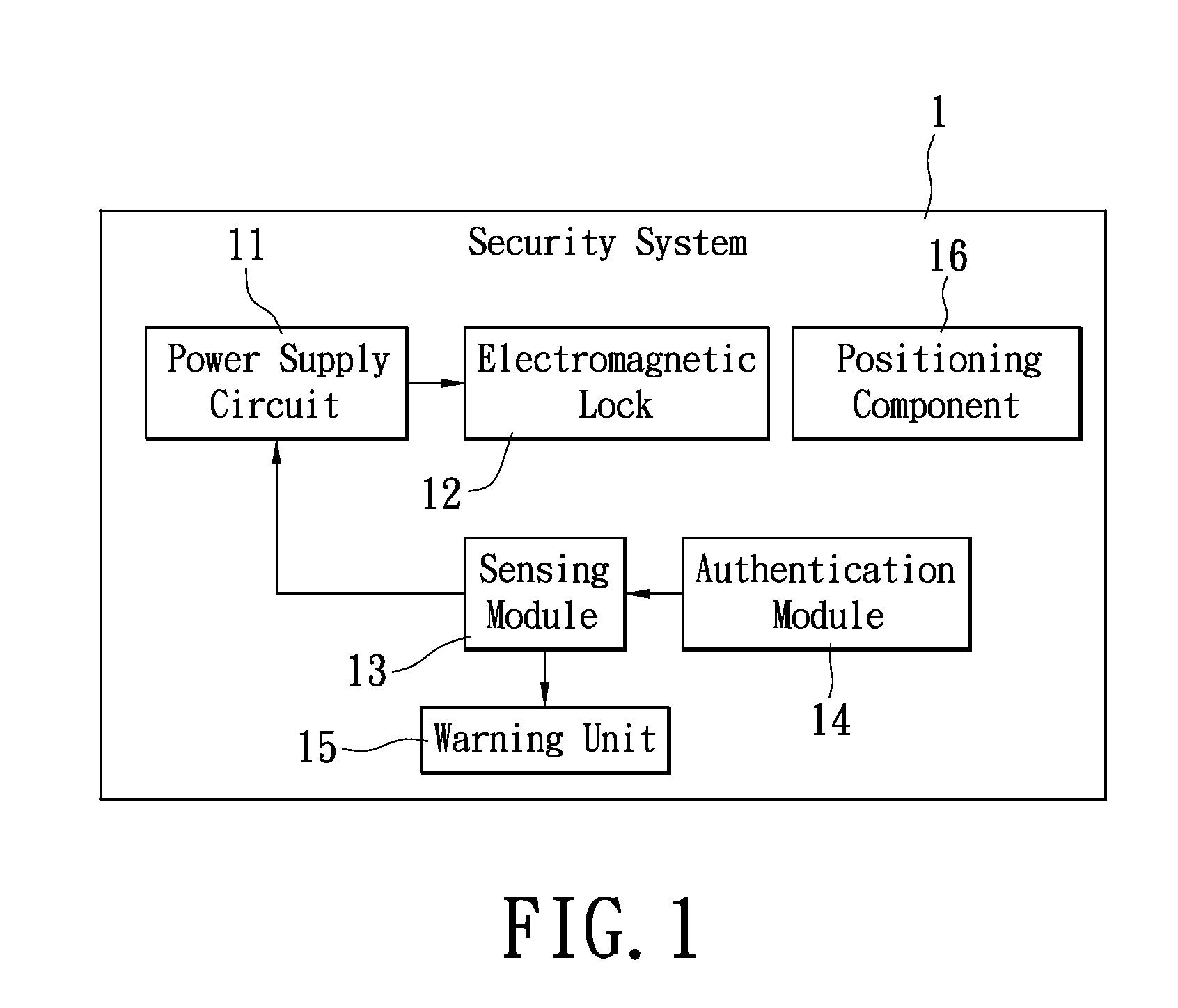
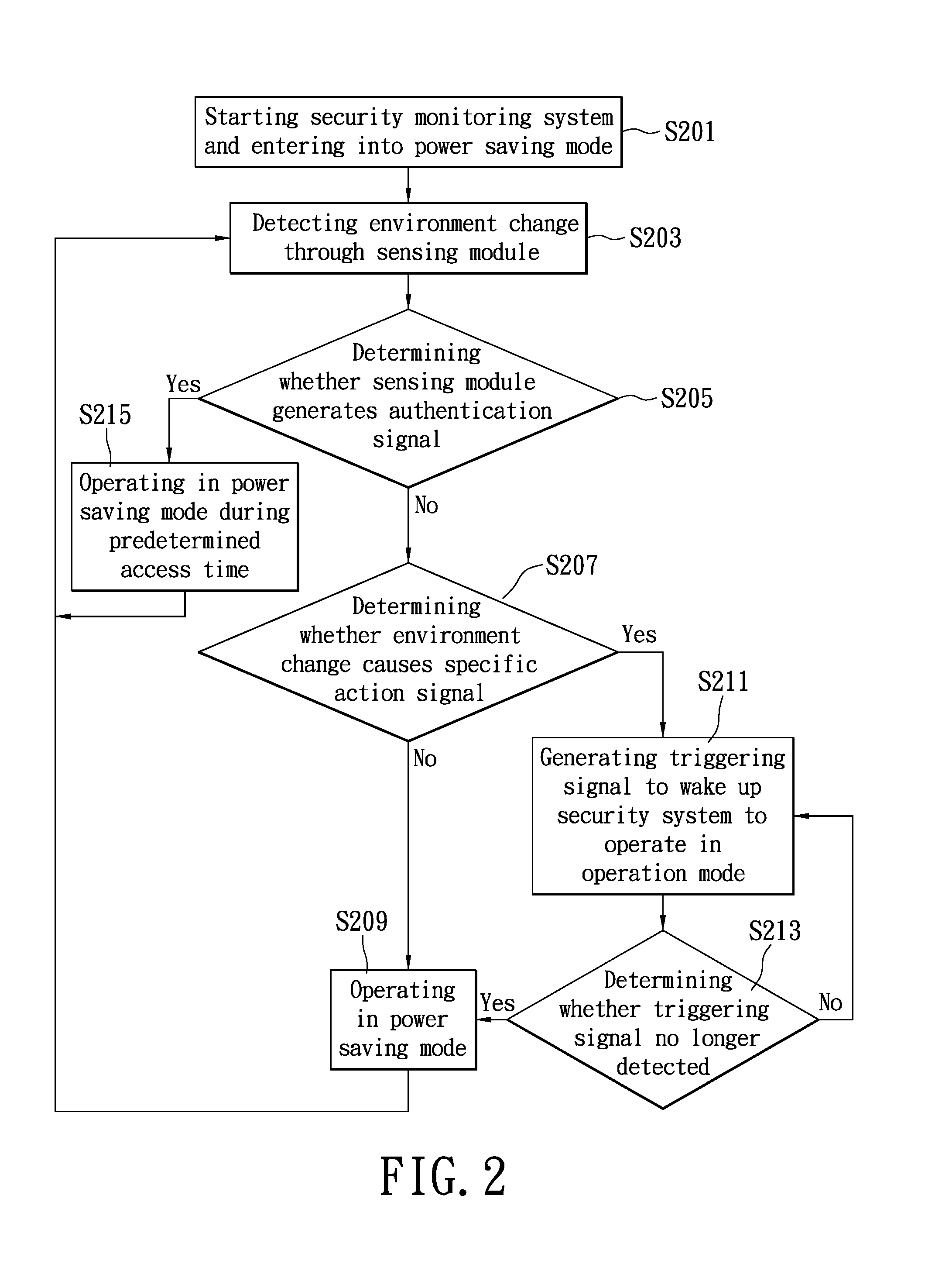
[0006]In view of the aforementioned issues, the technical problem that the present invention aims to resolve is to provide a security system meeting the requirements on both energy-saving and functional controls, allowing the security system to stay in a state requiring low power consumption, detecting any request for access by means of a sensing module, and thus controlling the locking / unlocking in the electromagnetic lock. In this way, the features of power saving as well as automatic prompt response to a triggering event can be achieved.

Problems solved by technology

However, the power consumed by an electromagnetic lock driven by a general direct current (DC) power supply may range from about several Watts (W) to roughly tens of Watts; in case of 12 Volts (V) DC power supply, it will continuously consume a current of hundreds of milliamperes (mA) for the electromagnetic lock to properly operate.
Therefore, the necessity of the continuous supply of the electric power for the conventional security system would leave the performance of the power consumption of the conventional security system a lot to be desired.
However, since the conventional security systems are unable to respond to any triggering event (e.g., access to the room behind the iron plate) immediately when operating in the standby mode the conventional security systems fail to meet the requirement of prompt response to the triggering event.
Besides, as manual operation is necessary for these conventional security systems to switch from the standby mode the goal of automatic control for the access may not be achieved.

Method used


Image

  • Security system with power saving feature and method thereof
  • Security system with power saving feature and method thereof
  • Security system with power saving feature and method thereof

Examples


Embodiment Construction

[0017]The present invention provides a security system with power saving feature and method thereof. More specifically, the present invention security system is configured to detect if there is any request for access before the full supply of electric power to the electromagnetic lock. Typically, the security system is applied to an access control systems, and an emergency doorway that is capable of allowing the passages of persons or goods when necessary. By means of the design disclosed herein, it is possible to allow the electromagnetic lock in the security system to remain in a lock state with limited power consumption; but, in case that a user approaches to or intends to pass through the monitored passage, then the security system immediately responds and supplies the required power (e.g., the full power supply) to the electromagnetic lock so that the electromagnetic lock could continue to operate in the lock state. Thus the requirements on both power saving and automatic contr...


PUM


Abstract

A security system with power saving feature includes an electromagnetic lock and a sensing module. The electromagnetic lock is for receiving a limited supply of an electric power supplied by a power supply circuit before a full supply of the electric power is delivered to the electromagnetic lock. The sensing module may cause the full supply of the electric power upon sensing a specific action signal caused by an environment change. Therefore, the electromagnetic lock may operate in a lock state with only the limited supply of the electric power and still operate in the same lock state even after the generation of the triggering signal. Thus, the time during which the electromagnetic lock operates with the full supply of the electric power is minimized, limiting the total power consumption accordingly.

Description

BACKGROUND OF THE INVENTION[0001]1. Field of the Invention[0002]The present invention relates to a security system, and more particularly, to a security system with power saving feature and method thereof.[0003]2. Description of Related Art[0004]In security industries or products (e.g., access control system), electromagnetic locks have been widely utilized. The conventional security system is required to uninterruptedly supply an electric power to the electromagnetic lock in order to generate a sufficient electromagnetic field for the electromagnetic lock to remain in a tight attachment onto an iron plate. As such, the iron plate could be placed in a “lock” state. On the other hand, when the iron plate is to be unlocked the electric power supplied to the electromagnetic lock may need to be stopped. However, the power consumed by an electromagnetic lock driven by a general direct current (DC) power supply may range from about several Watts (W) to roughly tens of Watts; in case of 12...

Claims


Application Information

Patent Timeline
IPC IPC(8): G05B23/02
CPCE05B1/0015E05B17/22E05B2047/0065H02J9/005E05C19/166G07C9/00134E05B2047/0068G07C9/32Y04S20/20Y02B70/30G08B29/28
Inventor LAI, CHIN-LUNLIAO, LI-SHIHTIEN, HAI-CHOULAI, CHIN-DING
Owner LAI CHIN LUN
Learn More