Transparent electrode and production method of same
a production method and electrode technology, applied in the field of transparent electrodes, can solve the problems of high production cost, inability to use devices that require such flexibility, and inability to obtain sufficient conductivity of transparent electrodes to function as electrodes, etc., and achieve low surface resistivity, high surface smoothness, and high light transmittance.
- Summary
- Abstract
- Description
- Claims
- Application Information
AI Technical Summary
Benefits of technology
Problems solved by technology
Method used
Image
Examples
example 1
Production of a Transparent Electrode
Production of Transparent Electrode TC-10
Inventive Example
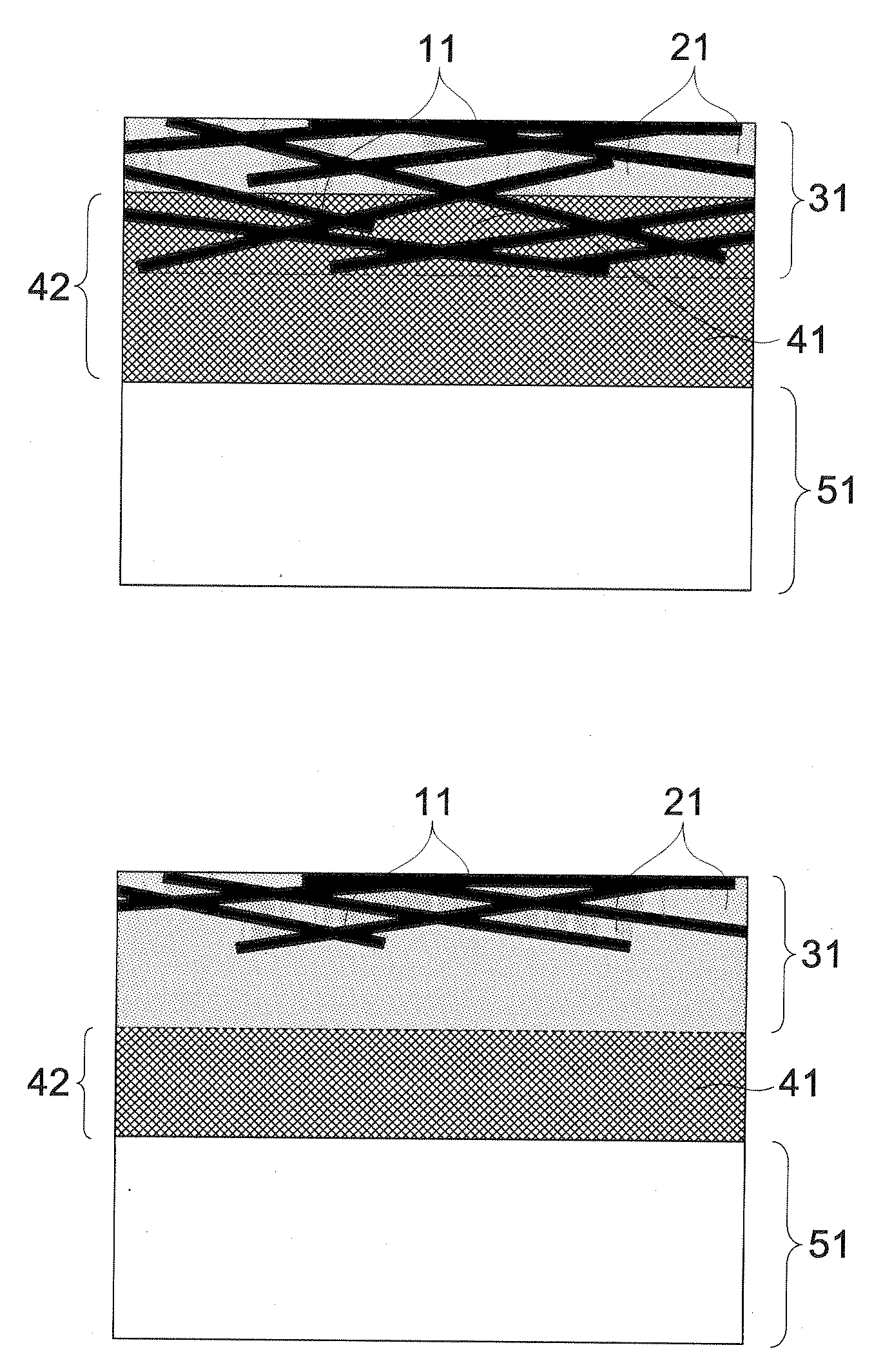
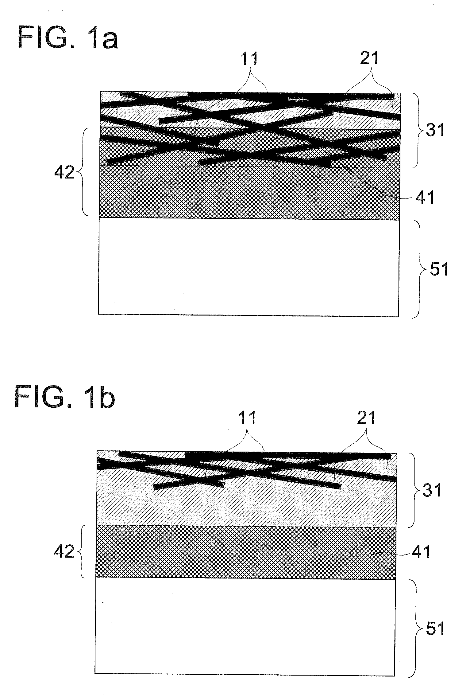
[0101]A transparent electrode was produced in accordance with the abovementioned desirable producing process of the transparent electrode of the present invention. As a mold releasing base material, a PET film with the surface smoothness Ry=35 nm and Ra=2 nm was used. The surface of the PET film was subjected to corona discharge treatment, thereafter, on the surface of the PET film, the silver nanowire dispersion liquid was coated such that the application amount of silver nanowires became 80 mg / m2, and dried, whereby a silver nanowire network structure was formed.
[0102]Furthermore, as the transparent conductive material, a dispersion liquid of PEDOT / PSS containing 5% of DMSO was over-coated on the abovementioned silver nanowire network structure such that a dried layer thickness became 100 nm, and was dried, thereafter the dried layer was subjected to heat treatment at 80° C. for three ho...
example 2
Production of Organic Electroluminescence Element (Organic EL Element)
[0127]Transparent conductive films TC-10 to TC-21 produced in Example 1 were employed as an anode electrode respectively, and Organic EL elements OEL-10 to OEL-21 were produced in the following ways respectively.
[0128]A coating liquid for forming a positive hole transporting layer was prepared in such a way that 4,4′-bis[(N-(1-naphthyl)-N-phenylamino)]biphenyl (NPD) of a positive hole transporting material was dissolved in 1,2-dichloroethane such that the content of NPD became 1 mass %. The prepared coating liquid was coated on each of the above anode electrodes by a spin coating apparatus, and then the coating layer was dried at 80° C. for 60 minutes, whereby positive hole transporting layers with a thickness of 40 nm were formed.
[0129]A coating liquid for forming a light emitting layer was prepared in the following ways. Polyvinyl carbazole (PVK) as a host material, and the following tree types of dopants were m...
example 3
Production of Transparent Electrode TC-31
Inventive Example
[0149]TC-31 was produced in the same way as the production method of TC-11 shown in Example 1 except that the transparent conductive material was changed to a dispersion liquid of tin oxide particles and an adjustment was made such that the dried film thickness became 300 nm.
Production of Transparent Electrode TC-41
Inventive Example
[0150]TC-41 was produced in the same way as the production method of TC-11 shown in Example 1 except that the conductive fibers was changed to a dispersion liquid of SWCNT (HiPcoR single layer carbon nanotubes manufactured by Unidym Corporation) and an adjustment was made such that the application amount of SWCNT became 10 mg / m2.
[0151]The produced transparent electrodes were made as an anode electrode respectively, organic EL elements were produced in the same way as Example 2, and the evaluation was conducted. As a result, it was confirmed that the whole EL elements emitted light evenly as with OL...
PUM
| Property | Measurement | Unit |
|---|---|---|
| Nanoscale particle size | aaaaa | aaaaa |
| Surface roughness | aaaaa | aaaaa |
| Electrical conductor | aaaaa | aaaaa |
Abstract
Description
Claims
Application Information
 - R&D
- Intellectual Property
- Life Sciences
- Materials
- Tech Scout
- Unparalleled Data Quality
- Higher Quality Content
- 60% Fewer Hallucinations
Browse by: Latest US Patents, China's latest patents, Technical Efficacy Thesaurus, Application Domain, Technology Topic, Popular Technical Reports.
© 2025 PatSnap. All rights reserved.Legal|Privacy policy|Modern Slavery Act Transparency Statement|Sitemap|About US| Contact US: help@patsnap.com


