Guide structure for stoppers

a technology of guide structure and stopper, which is applied in the direction of stopper feeding, conveyor, chute, etc., can solve the problems of the flexibility of the plant for preparing bottles and the difficulty of maintaining precision, so as to avoid the collection of dirt and facilitate the cleaning of the guide structure

Inactive Publication Date: 2011-01-27
SIDEL PARTICIPATIONS SAS
View PDF13 Cites 3 Cited by
  • Summary
  • Abstract
  • Description
  • Claims
  • Application Information

AI Technical Summary

Benefits of technology

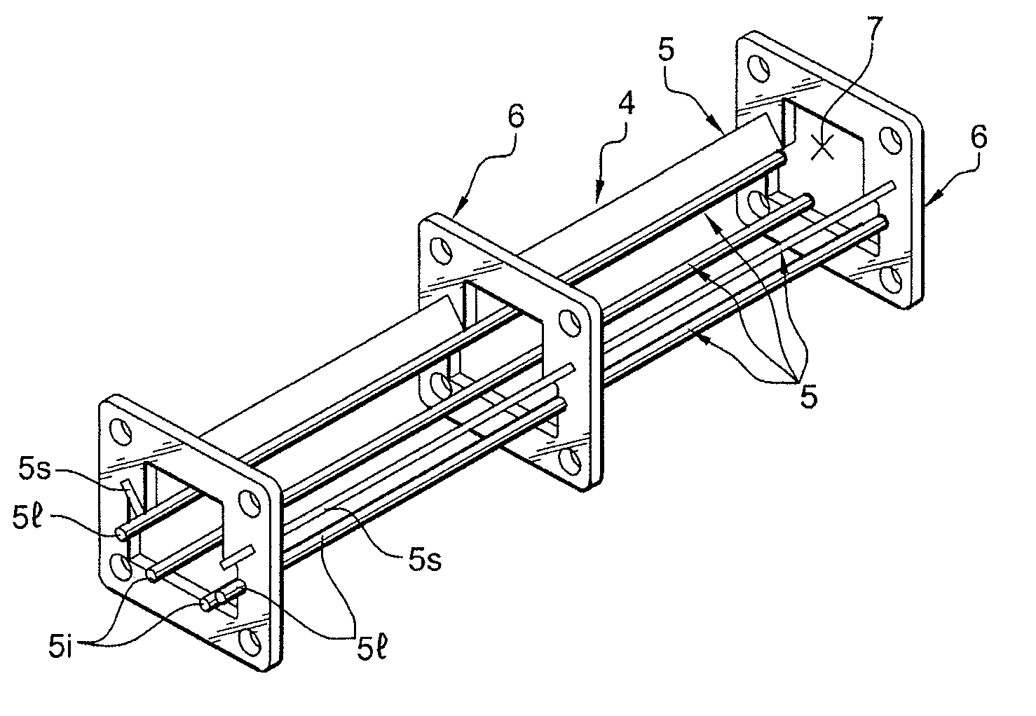
[0017]According to a preferential embodiment, the closing rails are in the form of bars having a trapezoidal section and the flat guide surface of these rails corresponds to a beveled design of one of the sides of said bar, said bar being, furthermore, inclined at an angle of around 45° with respect to the surface of the slideway of the tunnel, in order to avoid the collection of dirt and to facilitate cleaning of the guide structure.

Problems solved by technology

This precision is all the more difficult to maintain because the paths taken by the stoppers are never rectilinear and they are sometimes extremely tortuous.
The problems of guiding stoppers are always the same with, today, in addition, problems associated with the flexibility of the plants for preparing bottles.

Method used


Image

  • Guide structure for stoppers
  • Guide structure for stoppers

Examples


Embodiment Construction

[0027]The stopper (1), or top, shown in FIG. 1, corresponds to a conventional stopper (1c) for bottles made of thermoplastic, for example. It is in the form of a hollow cylinder having two flat surfaces.

[0028]The stopper (1) represented in FIG. 2 corresponds to a stopper (1t) commonly called a teat top. It comprises a cylindrical body (2), the dimensions of which correspond approximately to those of the stopper (1c), and this body (2) is surmounted by a protuberance (3); this protuberance (3), which forms the teat, can be relatively complicated in form and may comprise, as shown in the figure, a cap which covers the actual teat.

[0029]The two types of stopper (1c and 1t) can thus move in the guide structure (4) in the form of a tunnel, as shown in FIG. 2 and as shown in part in FIG. 3, in the form of a segment of tunnel.

[0030]This guide structure (4) has a C-shaped section with opposing lips extending towards one another and partially overlapping the top of the cylindrical body (2).

[...


PUM


Abstract

The guide structure for stoppers takes the form of a tunnel with a C-shaped section for trapping and guiding the cylindrical part of the stoppers (1c, 1t), which tunnel has opposing edges spaced out at a distance such as to allow the passage of the bulge (3) of the nipple-type stoppers (1t). This structure consists of filamentary rails (5) and of plates (6) with a hole through their central part shaped according to the profile of the stoppers that are to be transferred.

Description

FIELD OF THE INVENTION[0001]The present invention relates to a guide structure for stoppers and, more particularly, to a structure which is interposed between a preparation machine, where the stoppers are manipulated in order to be aligned correctly, and a drawing-off machine where they are put in position in order to close off bottles or flasks.DESCRIPTION OF THE PRIOR ART[0002]The conveying of stoppers from one station to another, between machines, generally takes place under simple gravity, but, in order to avoid the risk of jamming, the stoppers need to be guided with great precision in a sort of tunnel which consists of guide rails. This precision is all the more difficult to maintain because the paths taken by the stoppers are never rectilinear and they are sometimes extremely tortuous.[0003]As a result, guide structures are assessed and produced for every type of stopper and the precision which results therefrom makes it possible to obtain very high conveying speeds, with gre...

Claims


Application Information

Patent Timeline
Patent Type & Authority Applications(United States)
IPC IPC(8): B65G11/00
CPCB67B1/005B65G47/1407
Inventor HAMM, CAROLINERESTORI, PAOLOROTH, EMMANUEL
Owner SIDEL PARTICIPATIONS SAS
Why Eureka
Try Eureka