
Control system for internal combustion engine

a control system and internal combustion engine technology, applied in the direction of electric control, brake systems, instruments, etc., can solve the problems of engine output increase control upon vehicle deceleration, insufficient negative pressure, and inability to solve the problem of engine output increase control, etc., to achieve the effect of reducing the pressure parameter

Inactive Publication Date: 2011-01-27
HONDA MOTOR CO LTD
View PDF5 Cites 8 Cited by
  • Summary
  • Abstract
  • Description
  • Claims
  • Application Information

AI Technical Summary

Benefits of technology

[0008]The present invention was made contemplating the above described point, and an objective of the present invention is to provide a control system for an internal combustion engine having a plurality of intake systems corresponding to two or more cylinder groups, which is able to appropriately perform the engine output increase control upon vehicle deceleration, to prevent the negative pressure for securing the assisting force of the brake booster from becoming insufficient.
[0010]With this configuration, when performing the output increase control for increasing the engine output upon deceleration of the vehicle, the pressure parameter indicative of the assisting force generated by the brake booster is detected. The intake negative pressure is supplied to the brake booster from the first and second intake systems. If the detected pressure parameter is equal to or less than the first threshold value indicating that the assisting force of the brake booster has decreased, one of the first and second throttle valves respectively provided in the first and second intake systems is opened. Accordingly, the negative pressure is supplied to the brake booster from the intake system in which the throttle valve is not opened, thereby making it possible to secure the assisting force of the brake booster.
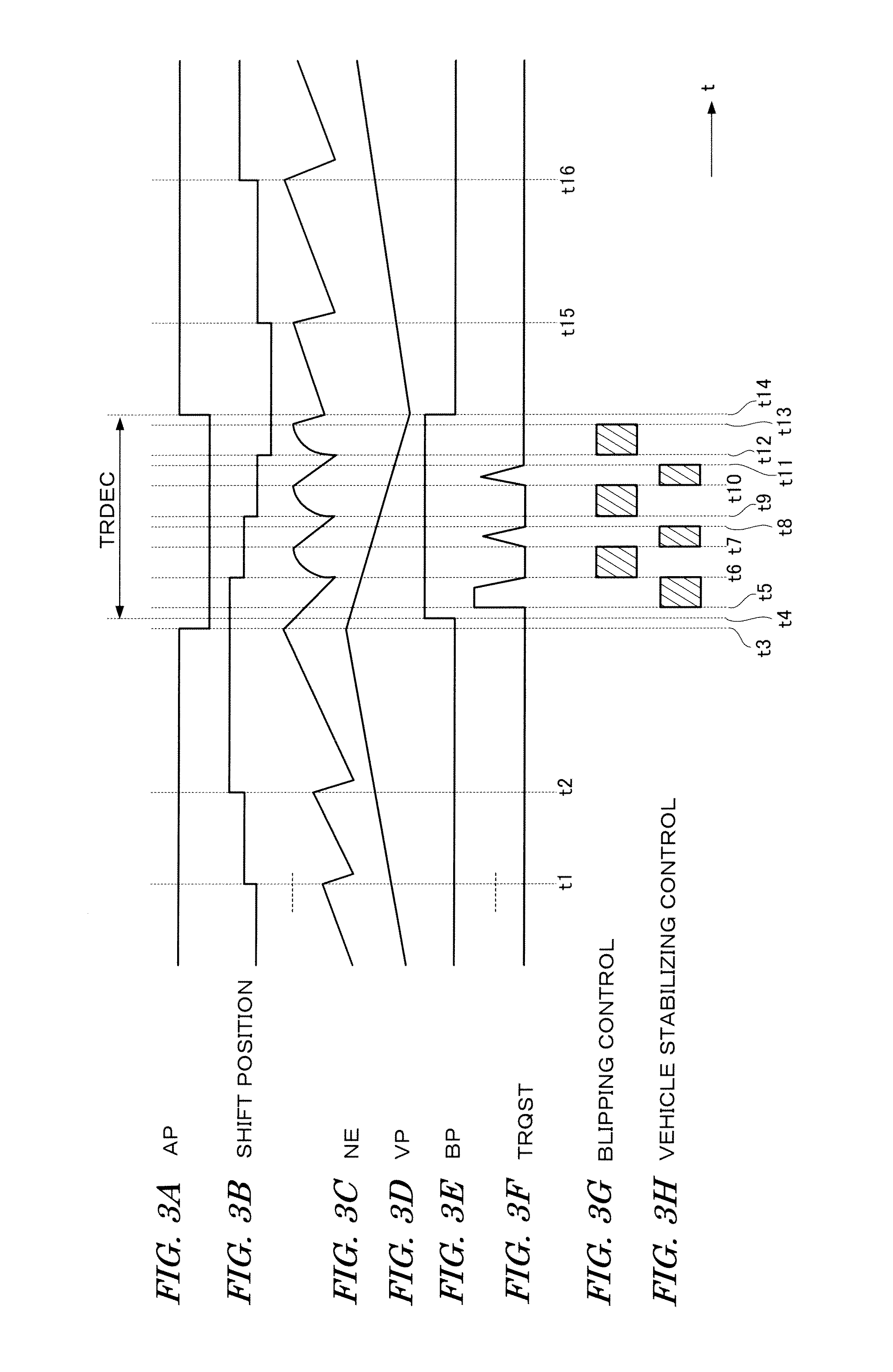
[0012]With this configuration, the vehicle stabilizing control in which the engine output is increased based on the driving wheel speed upon deceleration of the vehicle, is performed. If the driving wheels of the vehicle are locked by the braking upon vehicle deceleration, the driving wheel speed extremely decreases. In such case, by performing the vehicle stabilizing control that the throttle valve in one of the intake systems is opened to increase the engine output, it is possible to stabilize the vehicle behavior as well as to secure the negative pressure for the brake booster.
[0014]With this configuration, the one-throttle valve opening control is performed when performing the vehicle stabilizing control, and one of the one-throttle valve opening control and the two-throttle valve opening control is selected according to the pressure parameter when performing the blipping control. In the two-throttle valve opening control, both of the first and second throttle valve is opened to increase the engine output. It is possible to perform a part of the output increase control with the two-throttle valve opening control, if the pressure parameter is comparatively great, i.e., the degree of shortage of the assisting force of the brake booster is small. Therefore, by applying the one-throttle valve opening control to the vehicle stabilizing control and applying the two-throttle valve opening control to the blipping control when the pressure parameter is comparatively great, the engine output can rapidly be increased when performing the shift-down of the transmission, thereby rapidly completing the shift-down.
[0018]With this configuration, the shift-up of the transmission is performed with maintaining the driving force transmission through the clutch mechanism and the openings of the first and second throttle valve are controlled according to the engine output demanded by the driver. In the vehicle having the automatic transmission including the dual clutch mechanism, the throttle valves are opened according the demand engine output of the driver upon the shill-up of the transmission. Accordingly, the pressure parameter is reduced by performing the shift-up of the transmission. Therefore, it is more advantageous to the vehicle having the dual clutch mechanism to perform the engine output increase control upon deceleration of the vehicle with the one-throttle valve opening control.

Problems solved by technology

However, if the engine output is increased upon deceleration of the vehicle as described above, the negative pressure may become insufficient.
Such blipping control is also one of the factors which make the negative pressure insufficient.
Therefore, the problem due to the engine output increase control upon vehicle deceleration cannot be solved by the control system of JP-'474.

Method used


Image

  • Control system for internal combustion engine
  • Control system for internal combustion engine
  • Control system for internal combustion engine

Examples


Embodiment Construction

[0024]Preferred embodiments of the present invention will now be described with reference to the drawings.

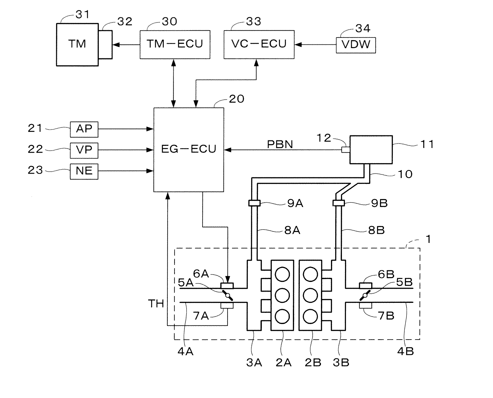
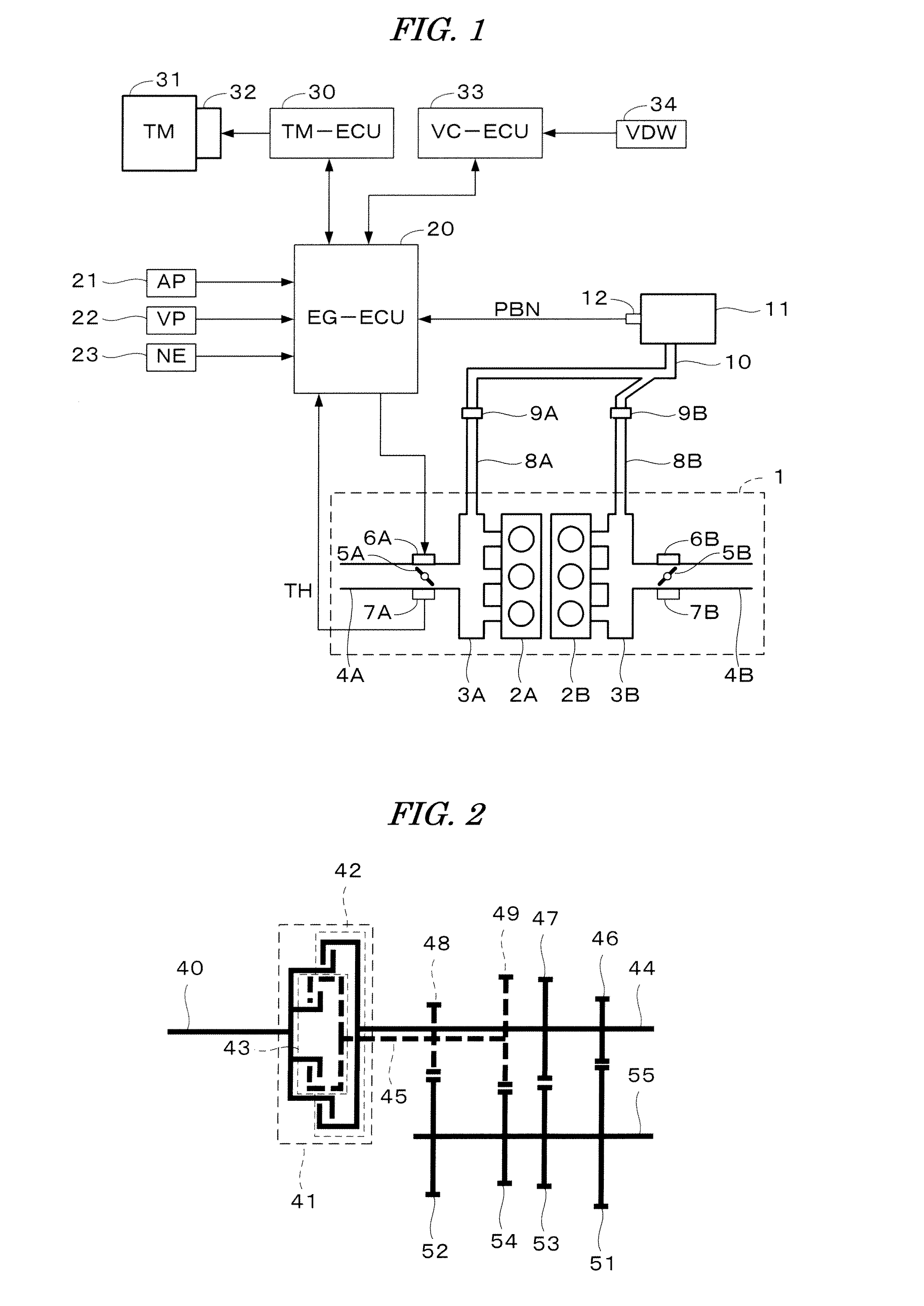
[0025]FIG. 1 shows a configuration of an internal combustion engine and a transmission mechanism for driving a vehicle according to one embodiment of the present invention and a control system therefor. A V-type six-cylinder internal combustion engine (hereinafter referred to as “engine”) 1 has a first bank 2A provided with #1-#3 cylinders (first cylinder group) and a second bank 2B provided with #4-#6 cylinders (second cylinder group).

[0026]An intake system corresponding to the first bank 2A includes a first chamber 3A, a first intake passage 4A, and branch passages connecting the first chamber 3A to #1-#3 cylinders. The first intake passage 4A is provided with a first throttle valve 5A. The first throttle valve 5A is provided with a first throttle valve opening sensor 7A for detecting an opening of the throttle valve 5A, and the detection signal of the sensor 7A is supplied to...


PUM


Abstract

A control system for an internal combustion engine having a plurality of cylinders including first and second cylinder groups. The first and second intake systems correspond respectively to the first and second cylinder groups, and first and second throttle valves are provided respectively in the first and second intake systems. An output of the engine is reduced upon deceleration of a vehicle driven by the engine. A pressure parameter indicative of an assisting force generated by a brake booster is detected. An intake negative pressure is supplied to the brake booster from the first and second intake systems. One of the first and second throttle valves is opened to increase the engine output when the pressure parameter is equal to or less than a first threshold value which indicates that the assisting force of the brake booster has decreased.

Description

BACKGROUND OF THE INVENTION[0001]1. Field of the Invention[0002]The present invention relates to a control system for an internal combustion engine, and particularly to a control system for an internal combustion engine which has a plurality of cylinders consisting of two or more cylinder groups, and a plurality of intake systems respectively corresponding to the cylinder groups.[0003]2. Description of the Related Art[0004]The brake booster for assisting the driver in operating the brake pedal of the automobile is widely used. The brake booster uses a negative pressure (a pressure which is lower than the atmospheric pressure) generated in the intake system of the internal combustion engine, to generate the assisting force. Japanese Patent Laid-open No. 2000-120474 (JP-'474) discloses a control system for an internal combustion engine which has two cylinder groups and two intake systems corresponding to the two cylinder groups. The engine and the brake booster shown in JP-'474 are co...

Claims


Application Information

Patent Timeline
IPC IPC(8): F02D41/00
CPCB60T13/52B60T17/02F02D11/10F02D9/109F02D9/02
Inventor OCHIAI, SINOBUOHYAMA, YASUNORIKAWAKAMI, AYAOKOAN, HIROSHI
Owner HONDA MOTOR CO LTD
Learn More