
Vibrating element apparatus

Active Publication Date: 2011-01-20
ROSEMOUNT TANK RADAR
View PDF6 Cites 9 Cited by
  • Summary
  • Abstract
  • Description
  • Claims
  • Application Information

AI Technical Summary

Benefits of technology

[0009]Preferably said method further includes mounting one or

Problems solved by technology

When the piezoelectric elements in the stack are subjected to a cyclic drive voltage, the same expand and contract between the compression screw and the diaphragm, deforming the diaphragm and causing the tines to vibrate.
A problem with existing designs is that, at point of manufacture, the stacks are assembled piece-by-piece into the apparatus.
This process is somewhat labour-intensive and, once assembled, the apparatus does not lend itself to repair, particularly on-site repair, in the event of failure in the piezoelectric stack assembly.
A further problem is that the plant served by the transducer may have to be drained before the transducer can be removed.
Whatever the case, transducer failure inevitably causes delay and expense, and may also give rise to health and safety issues.

Method used


Image

  • Vibrating element apparatus
  • Vibrating element apparatus
  • Vibrating element apparatus

Examples


Embodiment Construction

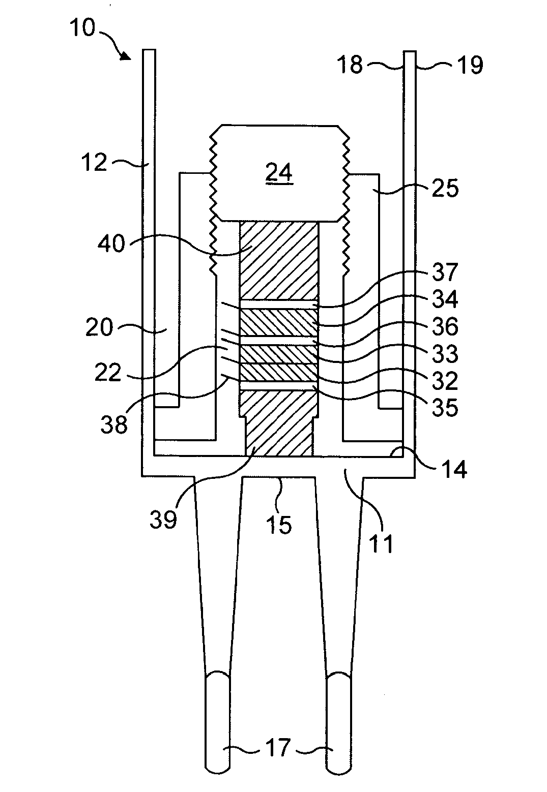
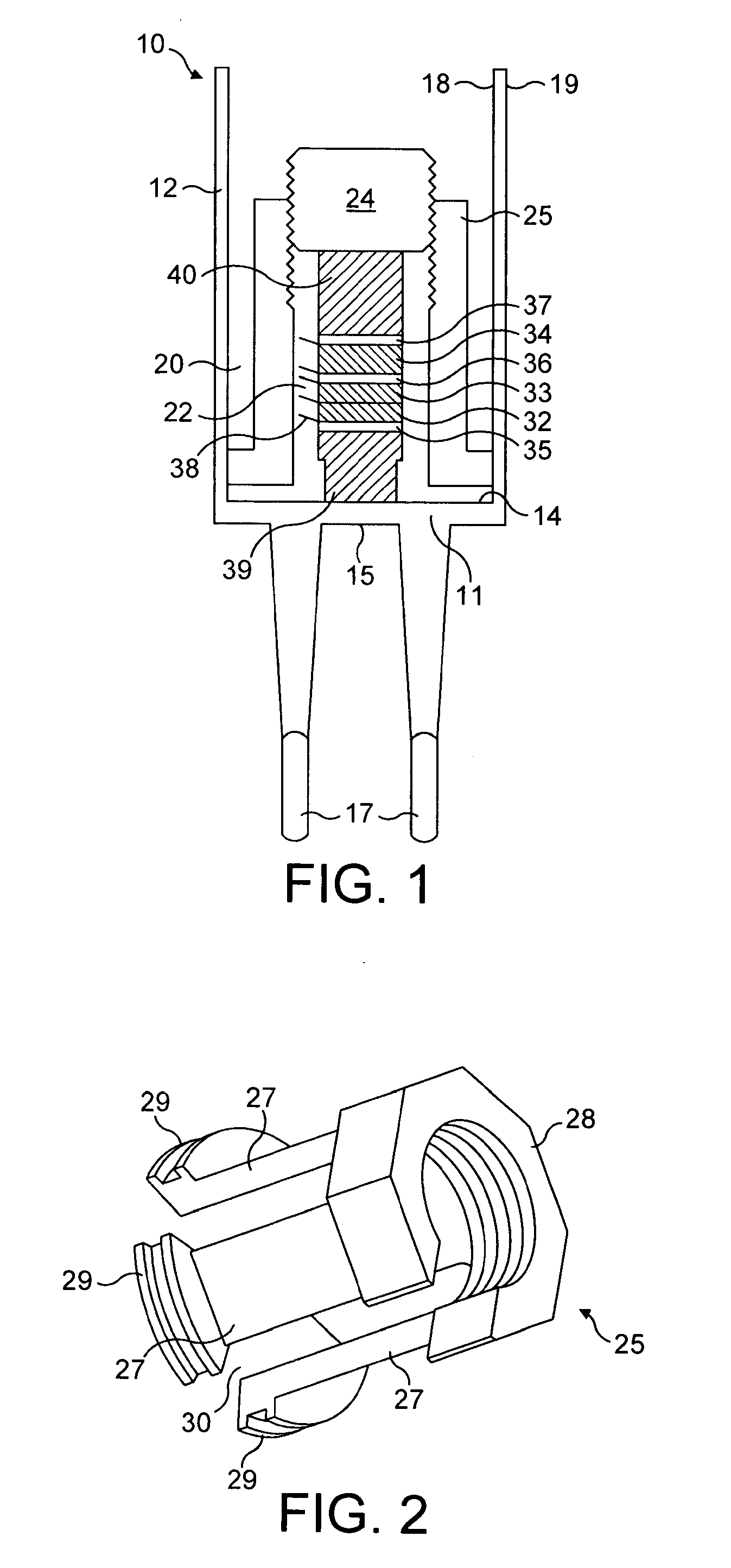
[0023]This invention provides a novel form of vibrating element apparatus which, in the case of the embodiment herein described, comprises a tuning fork-type liquid level detection transducer 10; and a method of forming the same. It will be appreciated, however, that a similarly configured device could be used to measure density and / or viscosity.

[0024]In the known manner the apparatus 10 includes a diaphragm 11 integrally formed with, and closing one end of, a cylindrical wall section 12. The diaphragm has an inner surface 14 and an outer surface 15. A pair of tines 17 extend from the outer surface 15.

[0025]The wall section 12 has an inner surface 18 and an outer surface 19. The inner surface 14 of the diaphragm and the inner surface 18 of the wall section combine to define a hollow body 20.

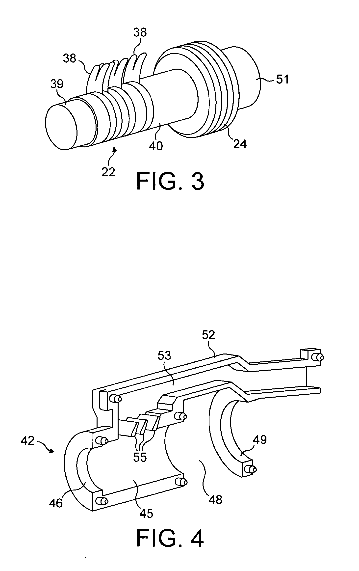
[0026]Located in the hollow body 20 are one or more piezoelectric elements which, in combination with spacers, insulators, connectors and the like comprise an assembly or stack 22 which is held i...


PUM

PropertyMeasurementUnit
Thermal propertiesaaaaaaaaaa

Abstract

The invention describes a vibrating element apparatus, preferably in the form of a tuning fork-type contact level transducer, and a method of forming the same. The tines of the transducer are vibrated by piezoelectric elements, which piezoelectric elements are arranged in a stack along with insulators and conductors to allow cyclic electrical signals to be applied thereto. The stack is provided as a sub-assembly allowing ready replacement in the field and 10 without disturbing the installation of the transducer in the plant which it serves.

Description

FIELD OF THE INVENTION[0001]This invention relates to a novel form of vibrating element apparatus and has been devised, in particular, to provide a vibrating fork-type fluid level transducer. However it will be appreciated by those skilled in the art, that the invention could also be applied to vibrating element apparatus configured to measure density and / or viscosity.BACKGROUND TO THE INVENTION[0002]Various forms of apparatus including one or more vibrating elements are well is known in the field of plant or process control, one example being a contact fluid level transducer. A typical contact fluid transducer includes a pair of spaced tines mounted on a diaphragm, the diaphragm in turn defining one end of a hollow cylindrical body. The tines are arranged to vibrate at a given frequency, typically their resonant frequency, and vibration is typically effected by displacing the centre of the diaphragm by means of a compressed stack of piezoelectric elements, located within the hollow...

Claims


Application Information

Patent Timeline
IPC IPC(8): H01L41/04B23P11/00
CPCB06B1/0618Y10T29/49826G01F23/2968
Inventor TURNER, ROY COLIN
Owner ROSEMOUNT TANK RADAR
Learn More