
Autonomous robotic platform

a robotic platform and autonomous technology, applied in the field of objects assembly and maintenance, can solve the problems of limiting the use of conventional machinery, complex structure assembly and maintenance, and requiring high-level dexterity systems

Active Publication Date: 2011-01-13
THE BOEING CO
View PDF46 Cites 91 Cited by
  • Summary
  • Abstract
  • Description
  • Claims
  • Application Information

AI Technical Summary

Benefits of technology

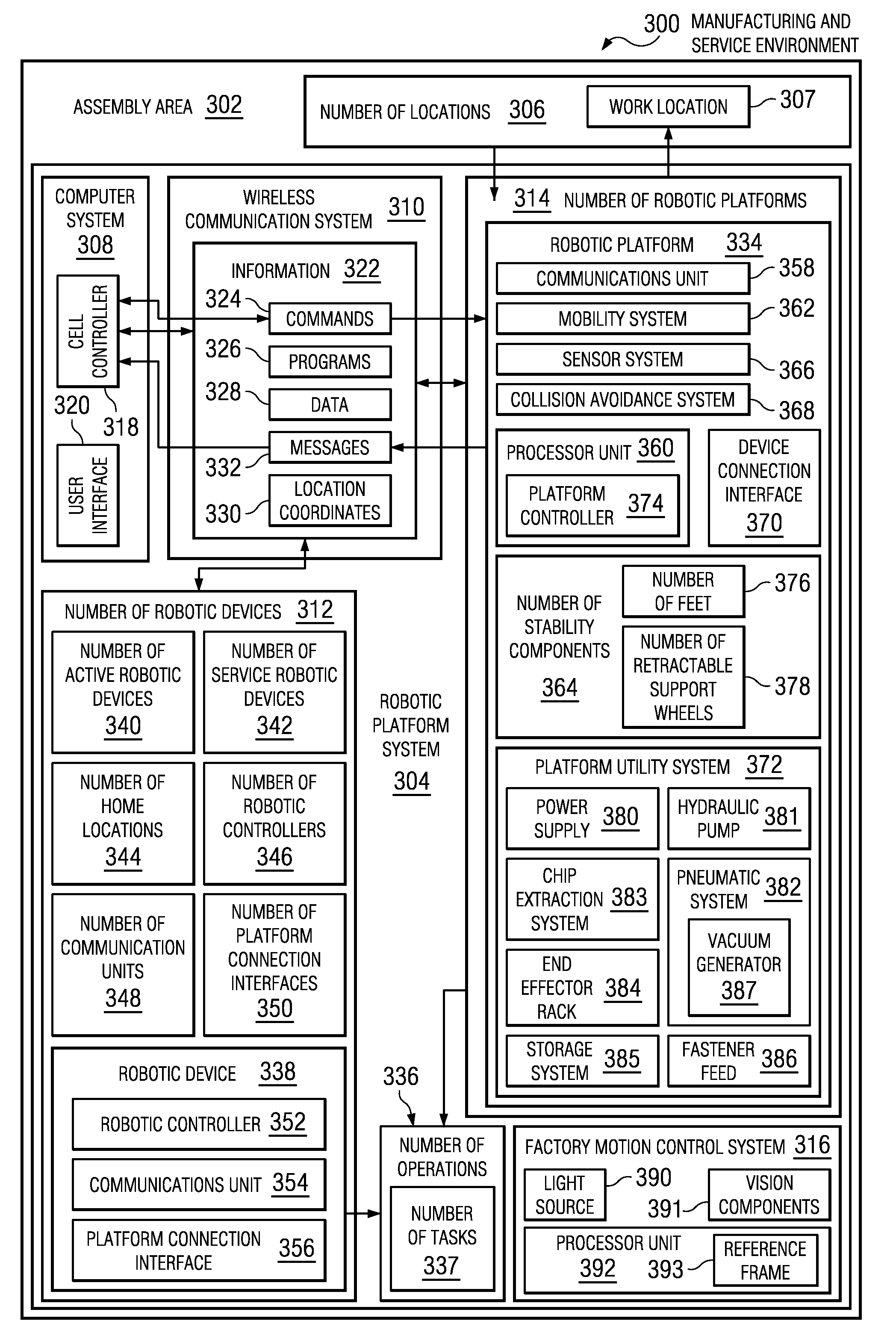
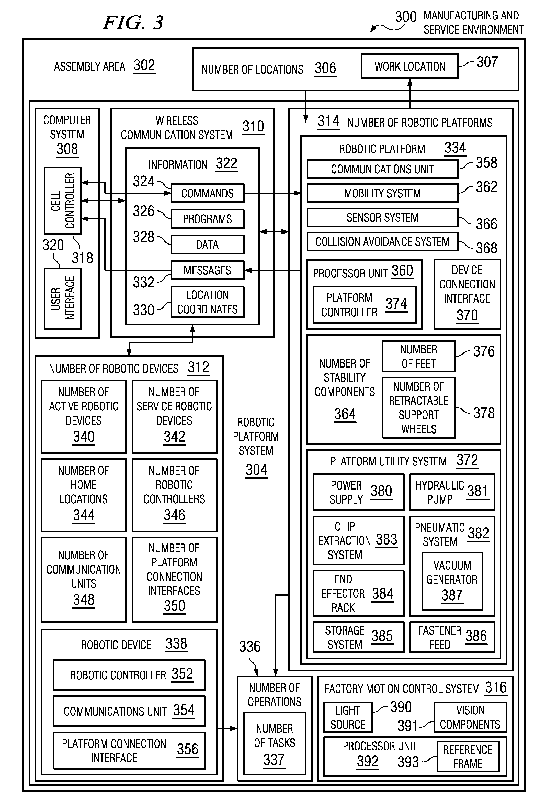
The patent describes an apparatus that includes a robotic platform, a wireless communications system, and a computer system. The robotic platform can move to different locations in an assembly area and interact with robotic devices. The wireless communications system allows the robotic platform to communicate with the robotic devices. The computer system exchanges information with the robotic platform and the robotic devices using the wireless communications system. The apparatus also includes a platform controller, a mobility system, a utility system, a device connection interface, and a communications unit. The platform controller moves the robotic platform to different locations. The mobility system controls the movement of the robotic platform. The utility system supplies utilities to the robotic devices. The device connection interface physically associates the robotic devices with the robotic platform. The technical effects of this invention include improved efficiency and flexibility in assembly processes, improved communication and interaction between robotic devices, and improved utilization of robotic resources.

Problems solved by technology

Structural assembly and maintenance may be complex and may require high level dexterity systems.
This requirement may limit the use of conventional machinery, such as many current robotic systems, for several assembly operations.
Fixed factory installed machines and robots may limit manufacturing and assembly flexibility.
This fixed installation limits flexibility in using these machines and robots in other areas within a manufacturing environment.
The size of these machines and robots for assembly of large structures, such as an aircraft wing or fuselage, may also limit applicability in manufacturing operations where space is at issue.
Likewise, the cost of these fixed factory machines and robots may become unaffordable in relation to the specific task the machine or robot is designed to perform.
For example, robotic systems installed on rails may have limited work volume and grow very large in size to work on aircraft structures.

Method used


Image

  • Autonomous robotic platform
  • Autonomous robotic platform
  • Autonomous robotic platform

Examples


Embodiment Construction

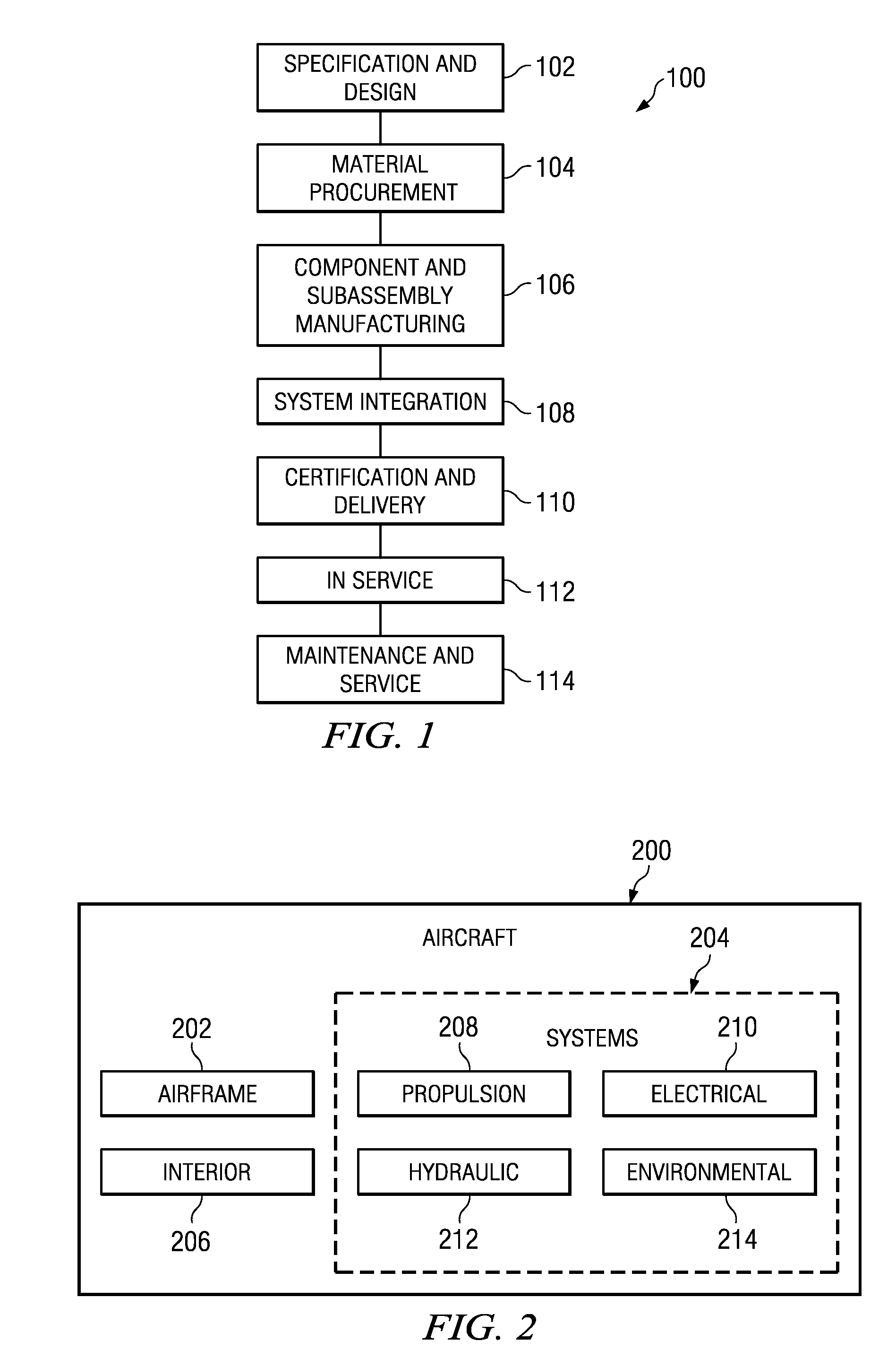
[0026]Referring more particularly to the drawings, embodiments of the disclosure may be described in the context of the aircraft manufacturing and service method 100 as shown in FIG. 1 and aircraft 200 as shown in FIG. 2. Turning first to FIG. 1, an illustration of an aircraft manufacturing and service method is depicted in accordance with an advantageous embodiment. During pre-production, aircraft manufacturing and service method 100 may include specification and design 102 of aircraft 200 in FIG. 2 and material procurement 104.

[0027]During production, component and subassembly manufacturing 106 and system integration 108 of aircraft 200 in FIG. 2 may take place. Thereafter, aircraft 200 in FIG. 2 may go through certification and delivery 110 in order to be placed in service 112. While in service by a customer, aircraft 200 in FIG. 2 may be scheduled for routine maintenance and service 114, which may include modification, reconfiguration, refurbishment, and other maintenance or ser...


PUM


Abstract

The different advantageous embodiments may provide an apparatus that may comprise a number of robotic platforms, a wireless communications system, and a computer system. The number of robotic platforms may be configured to move to a number of locations in an assembly area and interact with a number of robotic devices. The wireless communications system may be configured to provide communication with the number of robotic platforms and the number of robotic devices within the assembly area. The computer system may be configured to exchange information with the number of robotic platforms and the number of robotic devices using the wireless communications system.

Description

BACKGROUND INFORMATION[0001]1. Field[0002]The present disclosure relates generally to assembly of objects and, in particular, to an automated system for assembly and maintenance of objects. Still more particularly, the present disclosure relates to a method and apparatus for assembling aircraft structures using an autonomous robotic platform system.[0003]2. Background[0004]Structural assembly and maintenance may be complex and may require high level dexterity systems. This requirement may limit the use of conventional machinery, such as many current robotic systems, for several assembly operations. Structural assembly operations may be carried out manually or using machines and robots. Currently used machines and robots may be fixed on a factory floor or may move on rails to perform assembly tasks.[0005]Fixed factory installed machines and robots may limit manufacturing and assembly flexibility. These fixed machines and robots are dedicated to a few specific tasks, and may be hardwi...

Claims


Application Information

Patent Timeline
Patent Type & Authority Applications(United States)
IPC IPC(8): G05B19/418
CPCB25J9/08B25J5/007Y02P90/02
Inventor SARH, BRANKOAMIREHTESHAMI, DAVID H.
Owner THE BOEING CO
Learn More