Eureka AIR delivers breakthrough ideas for toughest innovation challenges, trusted by R&D personnel around the world.

3D Image Processing

a 3d image and processing technology, applied in the field of 3d image processing, can solve the problems of difficult interpretation and use for ongoing purposes, unsatisfactory for many practical applications, medical diagnosis,

Inactive Publication Date: 2011-01-13
MICROSOFT TECH LICENSING LLC
View PDF6 Cites 21 Cited by
  • Summary
  • Abstract
  • Description
  • Claims
  • Application Information

AI Technical Summary

Problems solved by technology

When these isosurfaces are rendered on a display the Bagginess and other artifacts make them difficult to interpret and use for ongoing purposes, such as medical diagnosis, object recognition, computer aided design and manufacture and other applications.
This approach often requires a very large kernel and strong filtration to diminish the artifacts and such filtration smoothes out fine details and produces surfaces which can be incompatible with the original binary volumes.
This is unsatisfactory for many practical applications such as medical diagnosis and manufacturing where it is required to obtain a 3D surface representation which depicts a 3D object in the scene being imaged with high fidelity.
This leads to surface representations that are significantly smoother than the original median isosurface but still suffer from visible artifacts and in addition the minimal area objective leads to artifacts on thin protrusions and sharp creases of the object.
In addition, this presents a difficult computational problem as the modification of the underlying three-dimensional mask is a non-convex problem, which can be computationally unstable and will not converge to the minimum representation without small step sizes, which increases the time needed to extract the surface.
Thus previously, computational resources required and time needed to produce good quality, smooth, 3D surface representations has been great.

Method used


Image

  • 3D Image Processing
  • 3D Image Processing
  • 3D Image Processing

Examples


Embodiment Construction

[0022]The detailed description provided below in connection with the appended drawings is intended as a description of the present examples and is not intended to represent the only forms in which the present example may be constructed or utilized. The description sets forth the functions of the example and the sequence of steps for constructing and operating the example. However, the same or equivalent functions and sequences may be accomplished by different examples.

[0023]Although the present examples are described and illustrated herein as being implemented in a 3D image processing system which carries out surface extraction, the system described is provided as an example and not a limitation. As those skilled in the art will appreciate, the present examples are suitable for application in a variety of different types of 3D image processing systems.

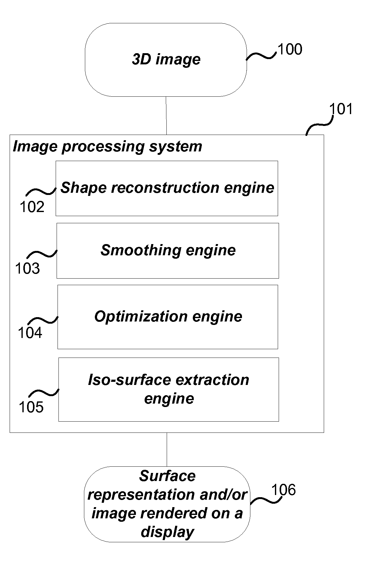
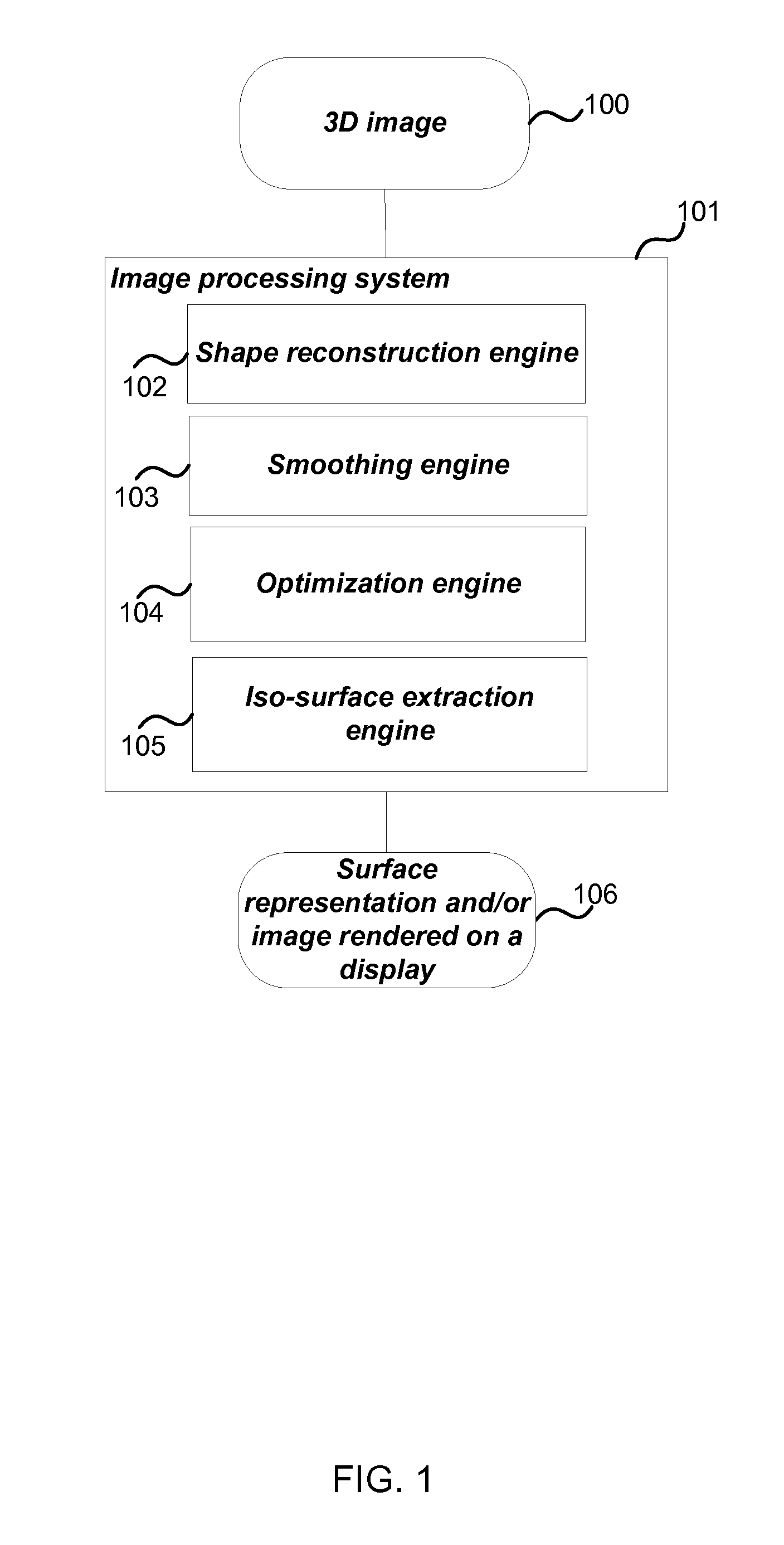
[0024]FIG. 1 is a schematic diagram of a three dimensional image processing apparatus implemented using a computer or processor of an...


PUM


Abstract

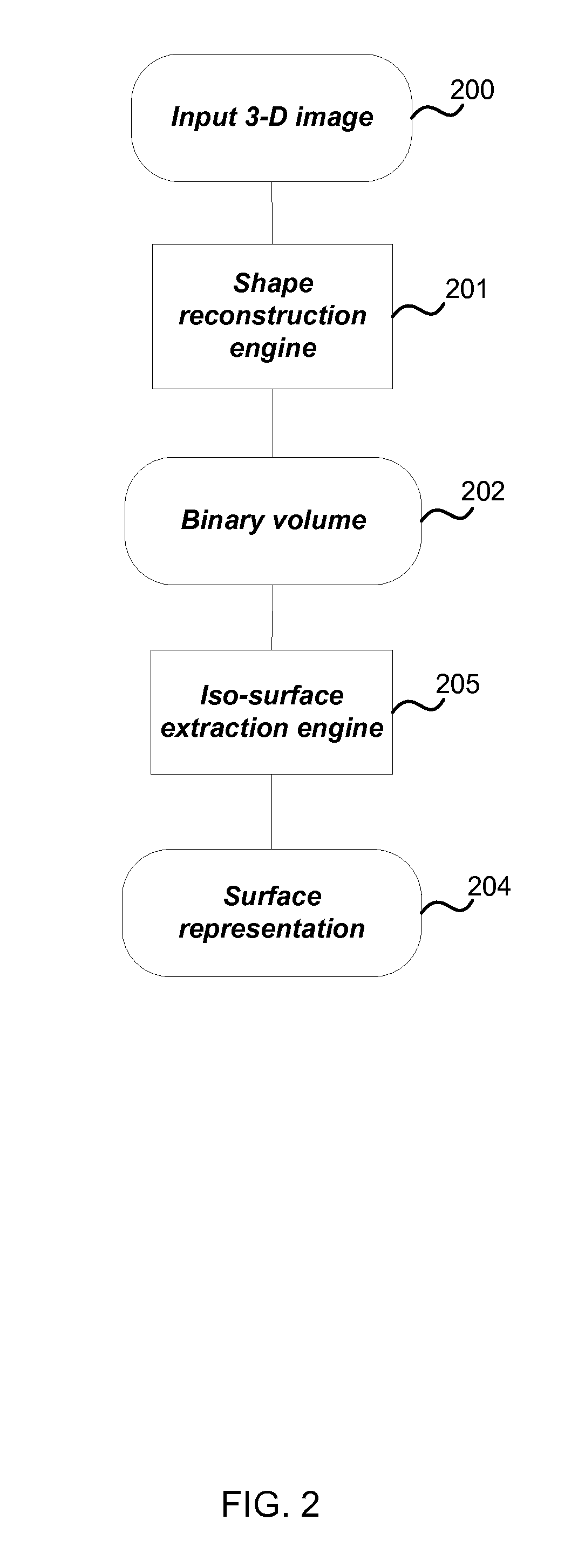
Three dimensional image processing is described for example, for digital rendering of real-world objects, medical imaging applications and digital effects rendering. In an example, a 3D image processing apparatus takes a binary volume representation of a three dimensional image and forms an embedding function substantially consistent with the binary volume. In examples, the embedding function is smoothed by regularizing the at least second order derivatives and optimized using a convex optimization engine. In an embodiment the optimized embedding function is used to create a surface representation of the three dimensional object using an iso-surface extraction engine. In another embodiment the surface representation may be directly rendered on a display using volume rendering techniques.

Description

BACKGROUND[0001]Three dimensional image processing is used in many application domains such as medical imaging, digital effects, virtual reconstruction and multiview reconstruction. For example, segmentation algorithms such as region growing, graph cuts or thresholding can be used to label image elements in a 3D image as belonging to either the foreground or the background. This is useful in application domains where it is required to separate an object of interest from a background in order to perform further measurements or processing. The output of these methods is a three dimensional image segmentation mask where all image elements comprising part of the foreground image are labeled with one value and all image elements comprising part of the background image are labeled with another value, this is known as a binary volume.[0002]The 3D image segmentation result can be represented in the form of a separating surface; that is, a surface which separates the background and the foreg...

Claims


Application Information

Patent Timeline
IPC IPC(8): G06K9/00G06T17/00G06K9/40
CPCG06T17/00
Inventor LEMPITSKY, VICTOR
Owner MICROSOFT TECH LICENSING LLC
Why Eureka
Eureka Blog
Learn More