Toric motor and lens barrel having the same incorporated therein

a technology of toric motors and lens barrels, which is applied in the direction of instruments, mechanical devices, optical elements, etc., can solve the problems of difficulty in downsizing toric motors, and achieve the effect of reducing the size of toric motors

Inactive Publication Date: 2011-01-13
RICOH IMAGING COMPANY
View PDF3 Cites 9 Cited by
  • Summary
  • Abstract
  • Description
  • Claims
  • Application Information

AI Technical Summary

Benefits of technology

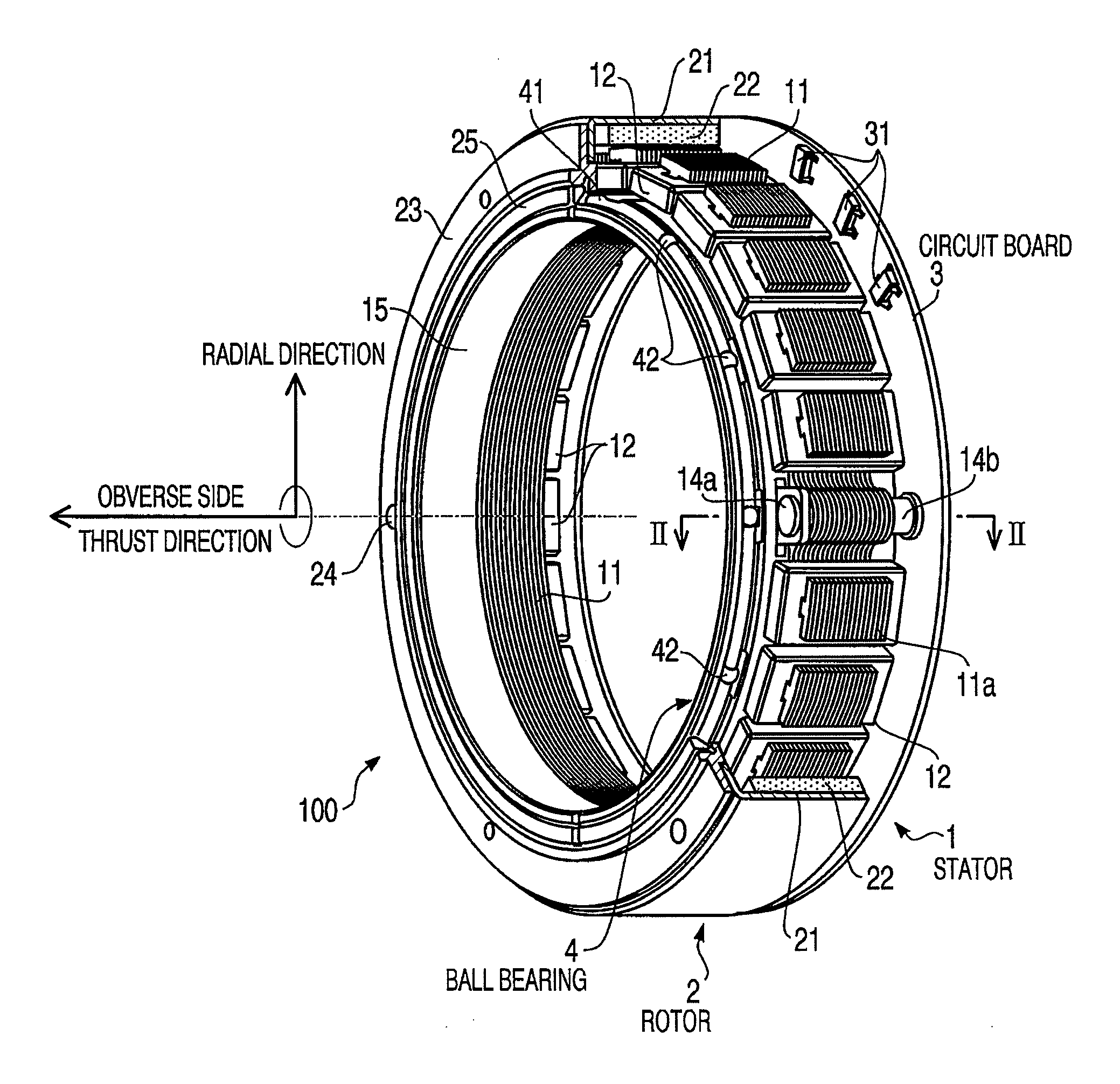
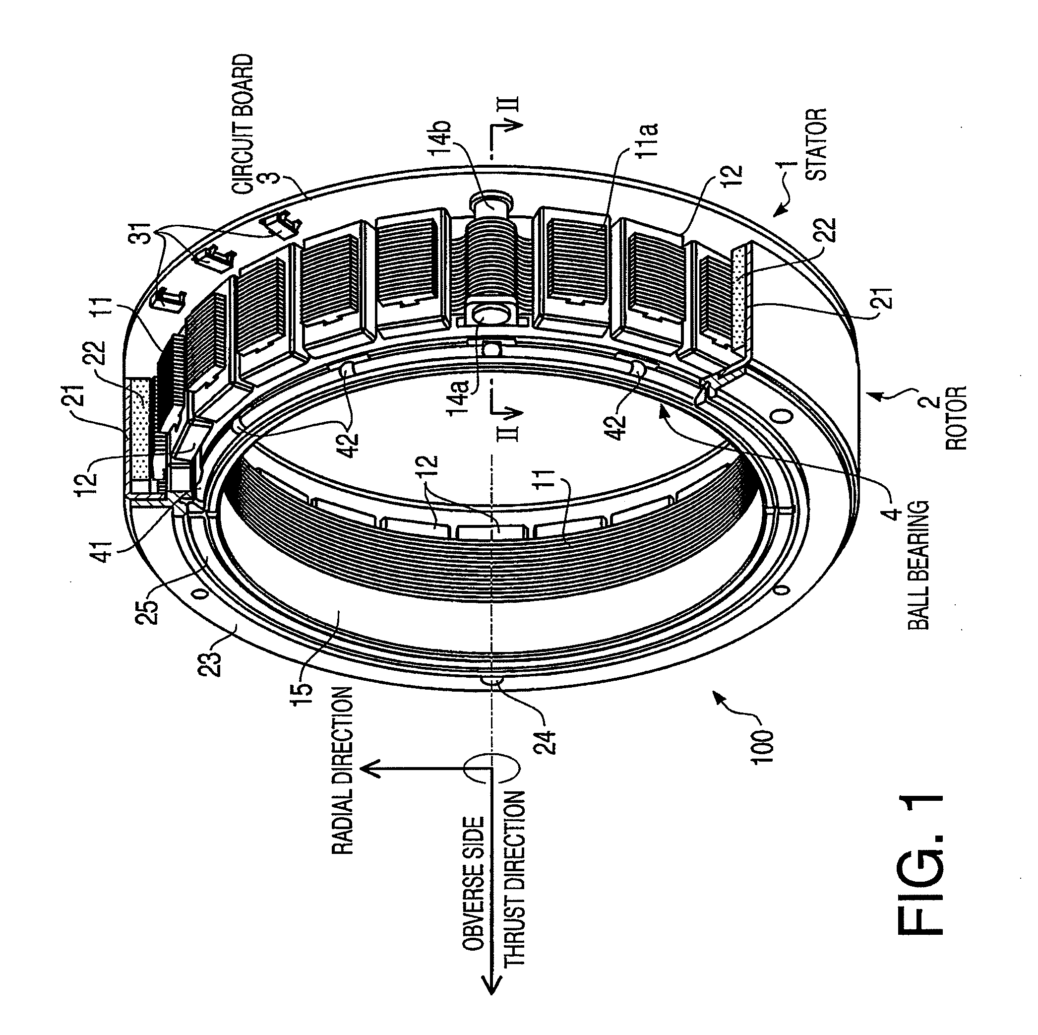
Aspects of the present invention are advantageous to provide one or more improved toric motors each of which makes it possible to reduce the sizes thereof and a lens barrel in which the toric motor is incorporated.

Problems solved by technology

It results in difficulties in downsizing the toric motor in the optical axis direction and the radial direction and thus in downsizing a lens into which the motor of this type is incorporated.

Method used


Image

  • Toric motor and lens barrel having the same incorporated therein
  • Toric motor and lens barrel having the same incorporated therein
  • Toric motor and lens barrel having the same incorporated therein

Examples


first practical example

FIG. 4 is a cross-sectional view schematically showing a first practical example in which the toric motor 100 of the embodiment according to aspects of the present invention is applied to a replaceable lens for a single-lens reflex camera. Inside an inner fixed tube 51 of a fixed tube 5 constituting a lens barrel, a lens frame 6 supporting a lens L is incorporated to be movable in an optical axis direction. A cam tube 7 is inserted in a small gap between the inner fixed tube 51 and an outer fixed tube 52 of the fixed tube 5 that is disposed a distance of the small gap away from the inner fixed tube 51 in the radial direction. The cam tube 7 is configured to be rotatable around an axis line of the lens barrel, i.e., the optical axis of the lens L. The cam tube 7 has a notch 71 provided at a distal end thereof. Further, the cam tube 7 has a required shape of cam groove 72 formed on a circumferential surface thereof. The inner fixed tube 51 has a guide groove 511, corresponding to the ...

second practical example

FIG. 5 is a cross-sectional view schematically showing a second practical example as a modification of the first practical example. In the second practical example illustrated in FIG. 5, the same elements as the first practical example shown in FIG. 4 have the same reference characters attached thereto, respectively, and explanation about them will be omitted. In the second practical example, a lock washer 25 is formed integrally with a cam tube 7. Specifically, the cam tube 7 has an outer flange 73 formed integrally with a distal end thereof, and the outer flange 73 has the lock washer 25 formed integrally with an outer end thereof in the radial direction. Here, although the outer flange 73 and the lock washer 25 are formed as an integrated member, the outer flange 73 and the lock washer 25 may be screwed together with respective threads provided thereto being engaged with each other. According to this configuration, it is needless to describe that when the toric motor 100 is rotat...


PUM


Abstract

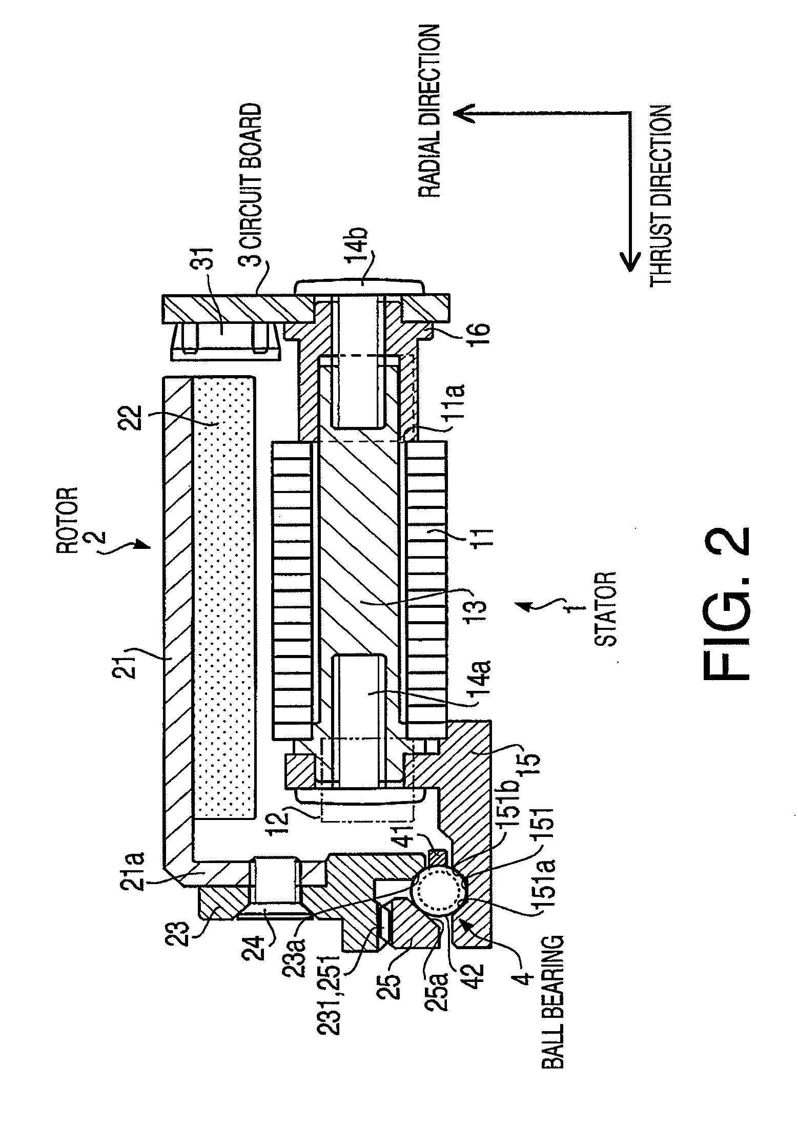
A toric motor includes a toric stator, a toric rotor configured to rotate along the stator, and a bearing configured to support the rotor so as to be rotatable relative to the stator, the bearing comprising a single-row four-point-contact angular ball bearing.

Description

BACKGROUND OF THE INVENTIONThe following description relates to one or more toric motors adapted to be incorporated into a lens barrel of a camera so as to drive a lens mechanism.A toric motor has been used as a driving source for automatically driving a lens mechanism of a lens-replaceable camera. The toric motor generally has a stator and a rotor formed to be ring-shaped, respectively, which rotor is driven to be rotated in a circumferential direction. As examples of a motor of this type, an ultrasonic motor and a brushless motor have been proposed. For instance, a surface wave motor is employed as a motor of this type in Japanese Patent Provisional Publication No. HEI10-319298 (hereinafter referred to as '298 Publication). In the surface wave motor, a toric rotor is disposed around an outer circumferential surface of a toric stator, and rotatably supported by bearings around the stator. Further, a pressing member presses the rotor against the stator in an optical axis direction s...

Claims


Application Information

Patent Timeline
Patent Type & Authority Applications(United States)
IPC IPC(8): G02B7/09H02K5/173
CPCG02B7/102H02K21/22H02K5/1735F16C19/166F16C33/581
Inventor KUROSAWA, YUICHISUZUKI, HIROAKI
Owner RICOH IMAGING COMPANY
Why Eureka
Try Eureka