
Catheterization System

Active Publication Date: 2010-12-30
MOZARC MEDICAL US LLC
View PDF99 Cites 49 Cited by
  • Summary
  • Abstract
  • Description
  • Claims
  • Application Information

AI Technical Summary

Benefits of technology

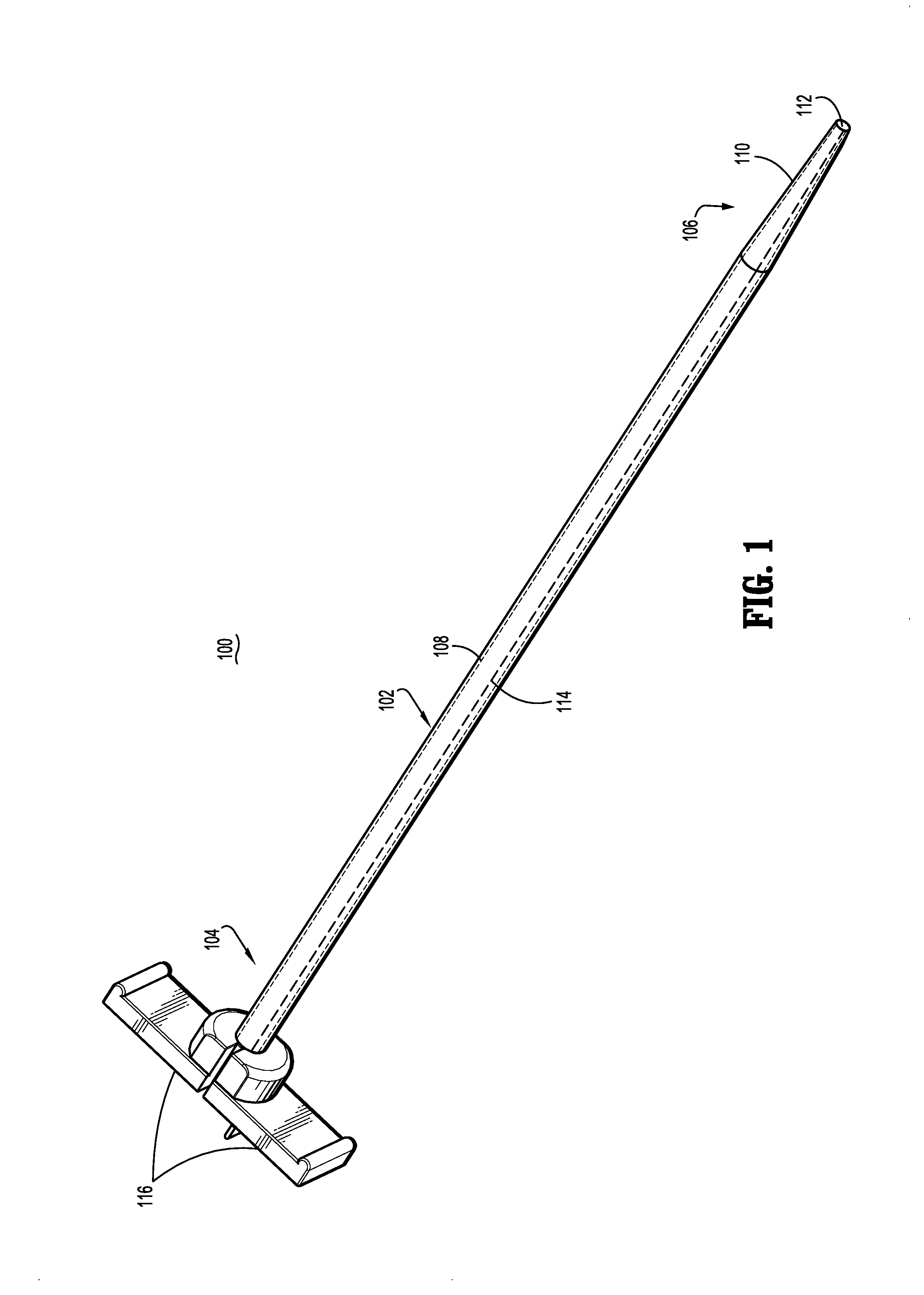
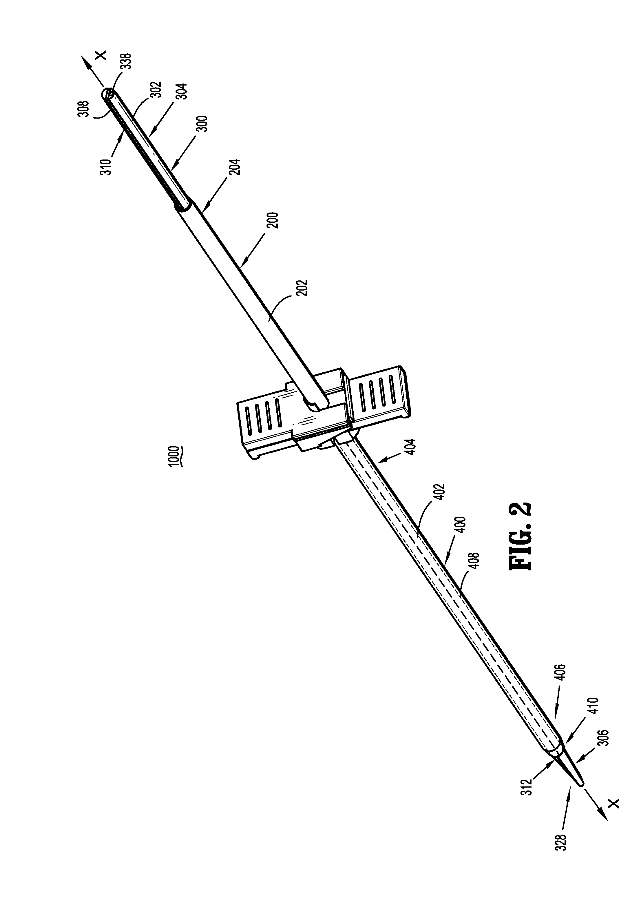
[0011]In one embodiment of the present disclosure, a catheterization system is disclosed including a catheter with a body having proximal and distal ends and defining first and second lumens extending therethrough, and a stylet. The catheter is formed from a first material, and the stylet is formed from a second, more rigid material such that positioning of the stylet within the catheter increases rigidity of the catheter.
[0015]In one embodiment, the catheterization system may further include a sheath having proximal and distal ends and defining a sheath lumen configured and dimensioned to receive the catheter. In this embodiment of the disclosed catheterization system, the stylet is dimensioned to extend beyond the distal end of the sheath when the stylet is positioned within the catheter such that the sheath forces the distal end regions of the first and second stylet portions into engagement with each other to define the penetrating portion of the stylet. To facilitate tearing of the sheath, the sheath may include a perforated section.
[0022]The stylet includes a first stylet portion with proximal and distal end regions, wherein the first stylet portion is configured and dimensioned for insertion into the first lumen of the catheter, and a second stylet portion with proximal and distal end regions, wherein the second stylet portion is configured and dimensioned for insertion into the second lumen of the catheter. Whereas the proximal end regions of the first and second stylet portions are separated from one another, the distal end regions of the first and second stylet portions are conjoined, to thereby inhibit relative longitudinal movement between the first and second stylet portions until a predetermined force is applied to the stylet.

Problems solved by technology

Acute catheters are designed to be placed in a patient under emergent circumstances where delays in placement are unacceptable, and typically remain in place for only a few days.

Method used


Image

  • Catheterization System
  • Catheterization System
  • Catheterization System

Examples


Embodiment Construction

[0067]Various exemplary embodiments of the present disclosure are discussed herein below in terms of medical catheters for the administration of fluids, i.e., withdrawal and introduction, to and from the body of a patient and, more particularly, in terms of a hemodialysis catheter. However, it is envisioned that the principles of the present disclosure are equally applicable to a range of catheter applications including surgical, diagnostic and related treatments of diseases and body ailments of a subject. It is further envisioned that the principles relating to the presently disclosed catheter may be equally applicable to a variety of catheter related procedures, such as, for example, hemodialysis, cardiac, abdominal, urinary, and intestinal procedures, in chronic and acute applications. Moreover, the presently disclosed catheter can be used for administration and removal of fluids such as, for example, medication, saline, bodily fluids, blood and urine.

[0068]In the following discu...


PUM


Abstract

The present disclosure relates to catheterization systems and components thereof. In one embodiment of the present disclosure, a catheterization system is disclosed that includes a catheter including a body with proximal and distal ends and defining first and second lumens extending therethrough, and a stylet. The stylet includes first and second stylet portions each having proximal and distal end regions, wherein the distal end regions of the first and second stylet portions together define a tapered penetrating portion. The first and second stylet portions are configured and dimensioned to be slidably positioned within the first and second lumens of the catheter, respectively. The first and second stylet portions extend from the proximal end of the catheter and beyond the distal end of the catheter, and are independently movable in relation to each other to facilitate selective removal of the first stylet portion and / or the second stylet portion from the catheter.

Description

CROSS-REFERENCE TO RELATED APPLICATIONS[0001]The present application claims the benefit of U.S. Provisional Patent Application Ser. No. 61 / 220,656, filed on Jun. 26, 2009, the entire contents of which are incorporated by reference herein.BACKGROUND[0002]1. Technical Field[0003]The present disclosure is directed to a catheter assembly adapted for use in a catheterization procedure. Specifically, the present disclosure relates to insertion sheaths and stylets for use during implantation of a catheter assembly during a hemodialysis procedure.[0004]2. Description of the Related Art[0005]Catheters are flexible medical instruments for use in the withdrawal and introduction of fluids to and from body cavities, ducts, and vessels. Catheters have particular application in hemodialysis procedures, in which blood is withdrawn from a blood vessel for treatment and subsequently returned to the blood vessel for circulation through a patient's body.[0006]Many hemodialysis catheters include multipl...

Claims


Application Information

Patent Timeline
IPC IPC(8): A61B17/34A61M25/09
CPCA61B17/32093A61B17/3415A61B2017/32113A61M1/3653A61M25/0041A61M25/0068A61M1/3661A61M25/0102A61M25/0668A61M29/00A61M2025/0031A61M2025/0037A61M2025/0681A61M25/0069A61M1/3659
Inventor BELLISARIO, MARCLOTITO, MARKGREEN, KURT E.MCELROY, GEOFFREY
Owner MOZARC MEDICAL US LLC
Learn More