
Fuel gas generator

a fuel gas generator and generator technology, applied in the direction of electric generator control, engine starters, machines/engines, etc., can solve the problems of high cost, inability to supply thermal energy to the first pneumatic cylinder, etc., and achieve the effect of improving electric generating efficiency and low cos

Inactive Publication Date: 2010-12-30
LUO CHIN KUANG
View PDF4 Cites 4 Cited by
  • Summary
  • Abstract
  • Description
  • Claims
  • Application Information

AI Technical Summary

Benefits of technology

[0007]Therefore, an object of the present invention is to provide a fuel gas generator that has enhanced electric generating efficiency at relatively low costs.

Problems solved by technology

When the thermal energy is generated from solar energy or terrestrial heat, unstable supply of the thermal energy to the first pneumatic cylinder 11 may occur.
When the thermal energy is generated by fuel combustion, in order to ensure stable supply of the thermal energy to the first pneumatic cylinder 11, continuous supply of fuel is necessary, thereby resulting in relatively high costs.

Method used


Image

  • Fuel gas generator
  • Fuel gas generator
  • Fuel gas generator

Examples


Embodiment Construction

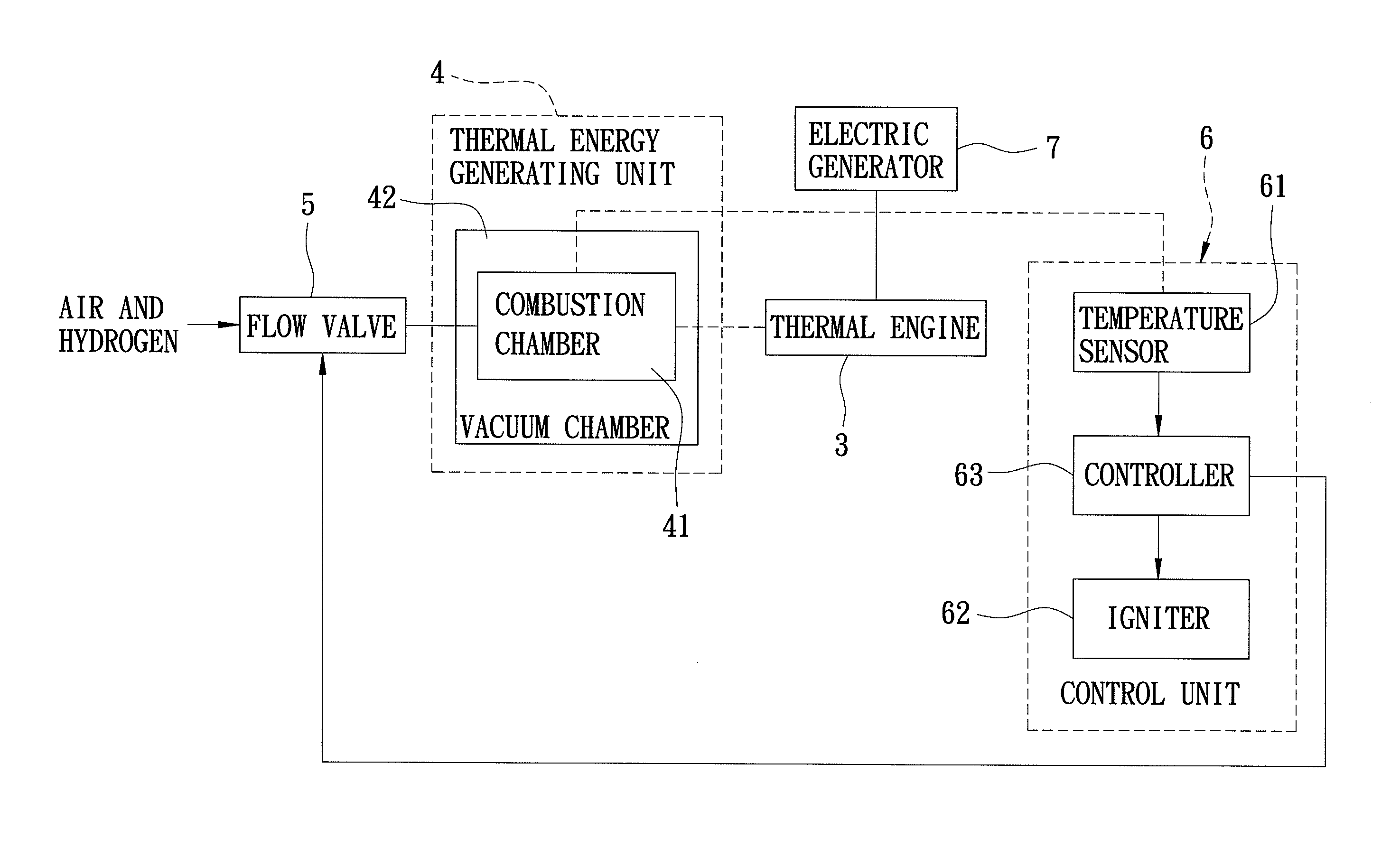
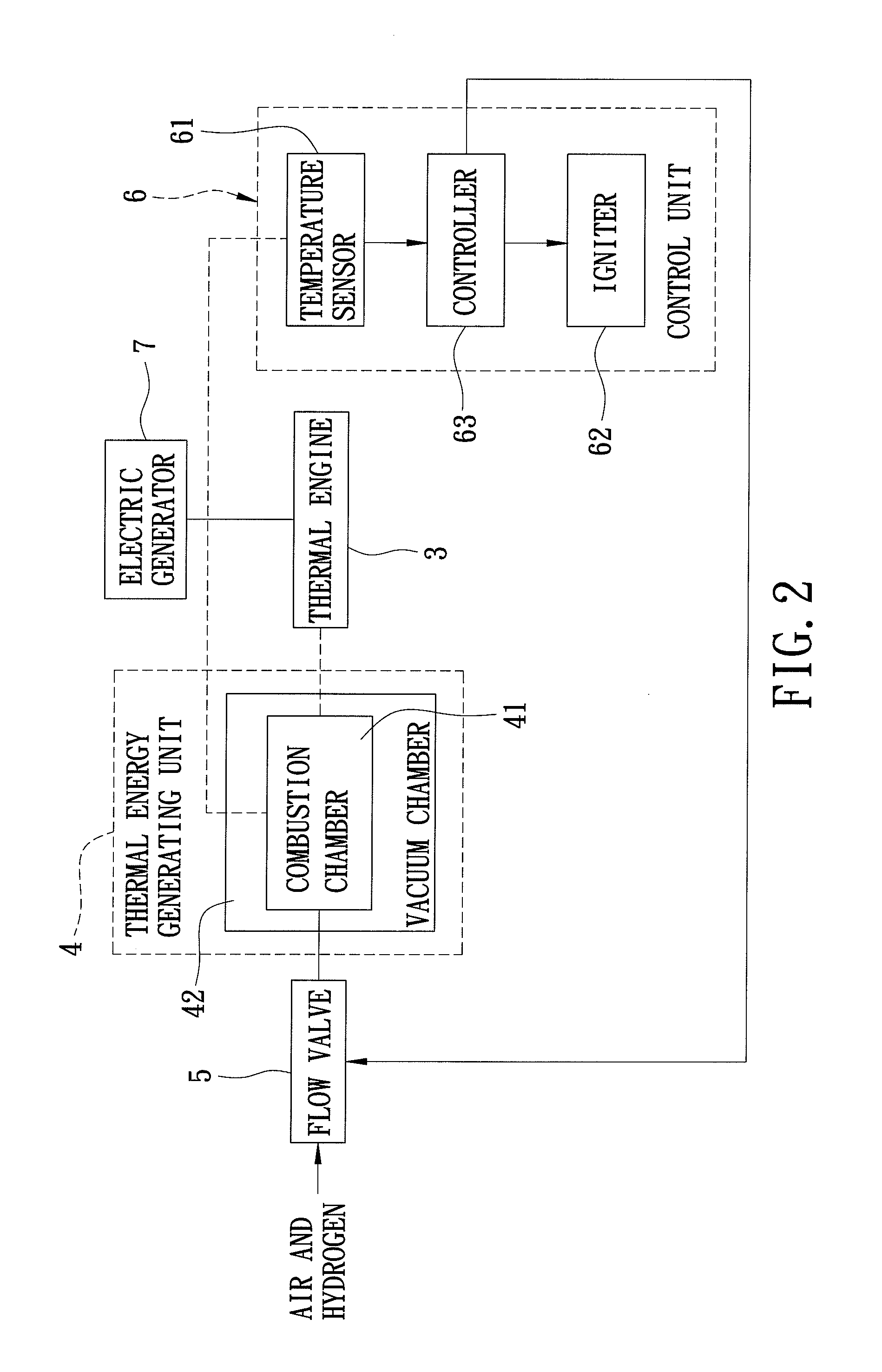
[0021]Referring to FIG. 2, the preferred embodiment of a fuel gas generator according to the present invention is shown to include a thermal engine 3, a thermal energy generating unit 4, a flow valve 5, a control unit 6, and an electric generator 7.

[0022]The thermal energy generating unit 4 includes a combustion chamber 41 and a vacuum chamber 42. The combustion chamber 41 is in thermal contact with the thermal engine 3 for generating thermal energy through combustion of air and fuel gas supplied thereto and for supplying the thermal energy to the thermal engine 3 such that the thermal engine 3 is driven to generate kinetic energy. In this embodiment, the fuel gas includes hydrogen such that a combustion product is water, thereby conforming to requirements for environmental protection. The combustion product can be discharged via a discharge passage (not shown) in spatial communication with the combustion chamber 41. In other embodiments, the fuel gas can be a hydrocarbon or natural...


PUM


Abstract

A fuel gas generator includes: a combustion chamber generating thermal energy through combustion of air and fuel gas therein, and supplying the thermal energy to a thermal engine such that the thermal engine is driven to generate kinetic energy that is converted into electrical energy by an electric generator; a temperature sensor for generating a sensing signal indicative of a temperature in the combustion chamber; and a controller for controlling a flow valve coupled to the combustion chamber based on the sensing signal such that the flow valve is switched to an OFF state upon detecting that the temperature is higher than a first temperature, thereby supplying the air and the fuel gas to the combustion chamber therethrough, and to an OFF-state upon detecting that the temperature is lower than a second temperature lower than the first temperature, thereby ceasing supply of the air and the fuel gas to the combustion chamber.

Description

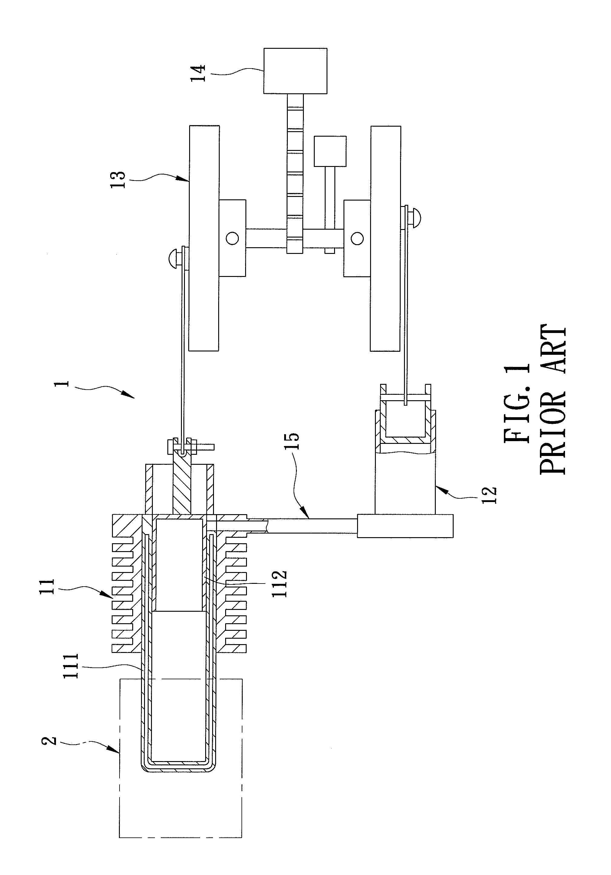
CROSS-REFERENCE TO RELATED APPLICATION[0001]This application claims priority of Taiwanese Application Nos. 098121623 and 098133167, filed on Jun. 26, 2009 and Sep. 30, 2009, respectively.BACKGROUND OF THE INVENTION[0002]1. Field of the Invention[0003]The invention relates to a generator, more particularly to a fuel gas generator.[0004]2. Description of the Related Art[0005]FIG. 1 illustrates a conventional thermal engine 1 disclosed in U.S. Pat. No. 6,779,341 and including a first pneumatic cylinder 11, a second pneumatic cylinder 12, a fluid pipe 15 intercommunicating fluidly the first and second pneumatic cylinders 11, 12, and a flywheel assembly 13 coupled to the first and second pneumatic cylinders 11, 12. Thermal energy from a thermal energy source 2 is applied to a cylinder body 111 of the first pneumatic cylinder 11 to result in an expansion stroke of the first pneumatic cylinder 11 and in rotation of the flywheel assembly 13. The expansion stroke of the first pneumatic cylin...

Claims


Application Information

Patent Timeline
Patent Type & Authority Applications(United States)
IPC IPC(8): H02P9/04F01K13/02
CPCF02G1/047
Inventor LUO, CHIN-KUANG
Owner LUO CHIN KUANG
Learn More