
Apparatus for controlling a bicycle suspension element

Active Publication Date: 2010-12-30
SHIMANO INC
View PDF7 Cites 112 Cited by
  • Summary
  • Abstract
  • Description
  • Claims
  • Application Information

AI Technical Summary

Benefits of technology

The present invention is about a device that controls the suspension of a bicycle. It includes a controller that adjusts the suspension based on the position of the bicycle seat. This invention has various benefits that improve the performance of the bicycle ride.

Problems solved by technology

However, such adjustments are made manually and usually require the rider to dismount the bicycle and set each parameter adjustment control device separately.

Method used


Image

  • Apparatus for controlling a bicycle suspension element
  • Apparatus for controlling a bicycle suspension element
  • Apparatus for controlling a bicycle suspension element

Examples


Embodiment Construction

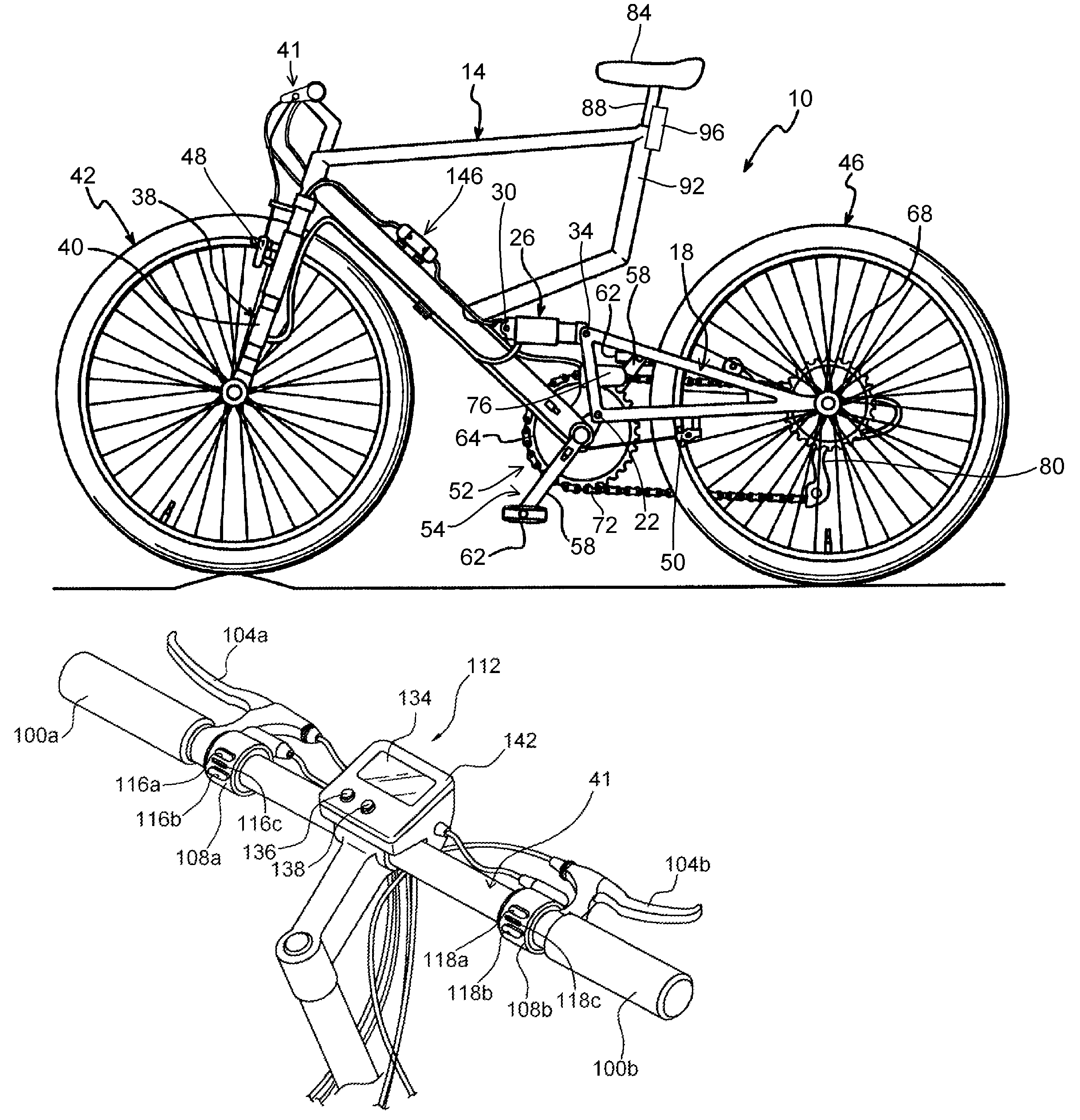
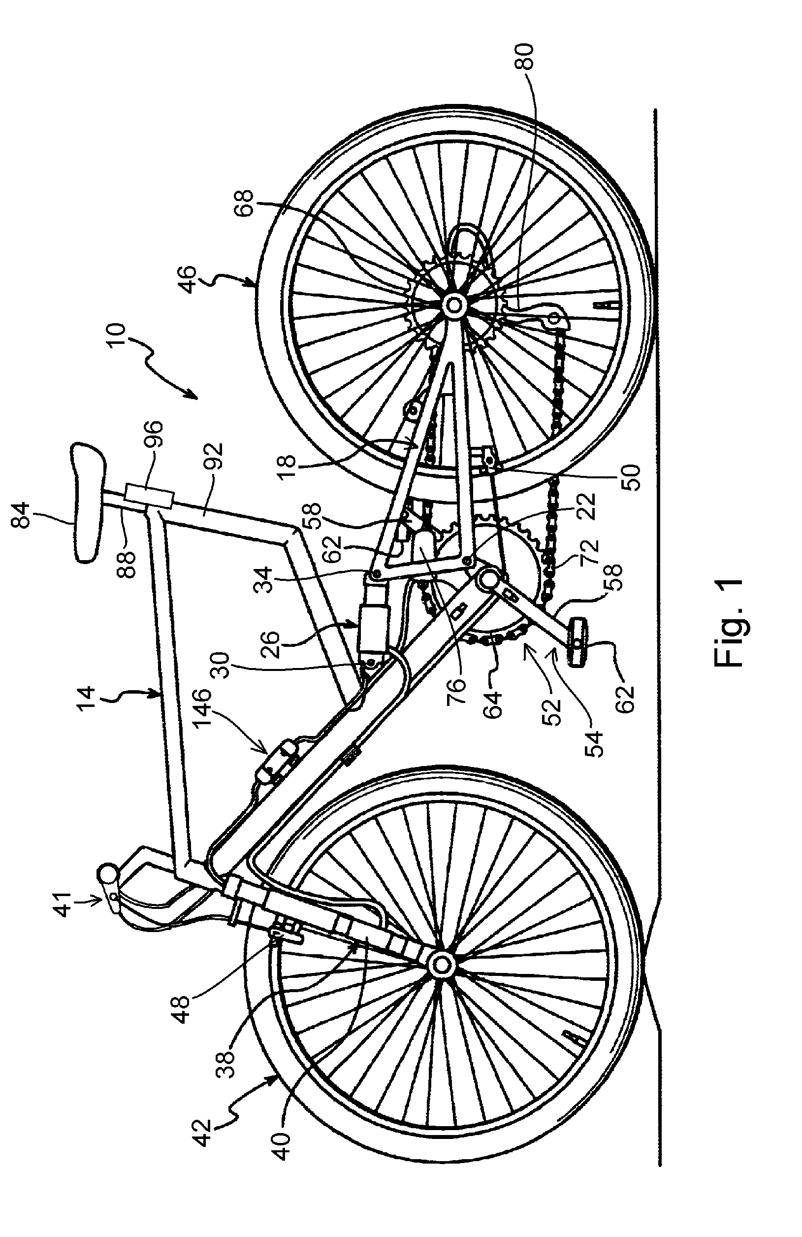
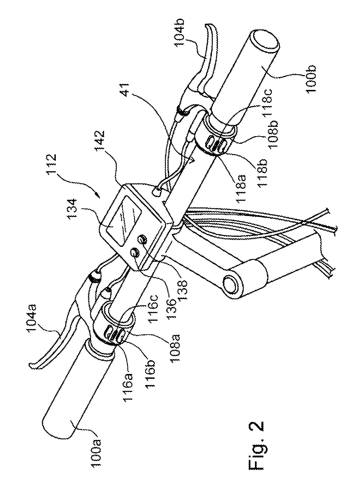
[0010]FIG. 1 is a side view of a bicycle 10 that includes particular embodiments of bicycle suspension elements. Bicycle 10 is a sport bicycle in the form of a mountain bicycle, and it comprises a front frame portion 14, a rear frame portion 18 pivotably coupled to front frame portion 14 through a pivot shaft 22, a rear suspension element 26 with a front end pivotably coupled to front frame portion 14 through a pivot shaft 30 and a rear end pivotably coupled to rear frame portion 18 through a pivot shaft 34, a front fork 38 rotatably mounted to front frame portion 14 and including a pair of front suspension elements 40, a handlebar assembly 41 mounted to the upper part of fork 38, a front wheel 42 rotatably attached to the lower part of fork 38, a rear wheel 46 rotatably attached to the rear of rear frame portion 18, a front brake 48 for braking front wheel 42, a rear brake 50 for braking rear wheel 46, and a drive mechanism 52.

[0011]Drive mechanism 52 comprises a pedal crank 54 tha...


PUM


Abstract

An apparatus for controlling a bicycle suspension element includes a suspension parameter controller that provides a suspension parameter controlling signal to control an operating parameter of the bicycle suspension element in response to a bicycle seat position.

Description

BACKGROUND OF THE INVENTION[0001]The present invention is directed to bicycles and, more particularly, to various features of an apparatus for controlling a bicycle suspension element.[0002]Bicycle suspensions often comprise front and rear suspension elements. The front suspension element typically comprises a pair of shock absorbers that form portions of the legs of the front wheel fork, and the rear suspension element typically comprises a shock absorber with one end mounted to the front portion of the frame and another end mounted to a pivoting rear swing arm that supports the rear wheel. In any case, the shock absorber usually comprises an outer tubular suspension member and an axially movable telescoping inner tubular suspension member. A piston is coupled to the inner tubular suspension member, wherein the piston has an outer peripheral surface that sealingly and slidably engages the inner peripheral surface of the outer tubular suspension member to form a compression chamber ...

Claims


Application Information

Patent Timeline
Patent Type & Authority Applications(United States)
IPC IPC(8): B60G17/015
CPCB62J99/00B62K25/04B62K2201/08B62K2025/044B62K2025/045B62K25/286B62J50/22
Inventor HARA, NOBUKATSUSUZUKI, TOSHIKUNI
Owner SHIMANO INC
Learn More