
Air bus transportation system

a technology for air buses and transportation systems, applied in the field of air bus transportation systems, can solve the problems of increasing rail transportation and inherently limited speed of conventional mass transportation, and achieve the effect of generating aerodynamic li

Inactive Publication Date: 2010-12-30
SIMON ABNER J
View PDF22 Cites 12 Cited by
  • Summary
  • Abstract
  • Description
  • Claims
  • Application Information

AI Technical Summary

Benefits of technology

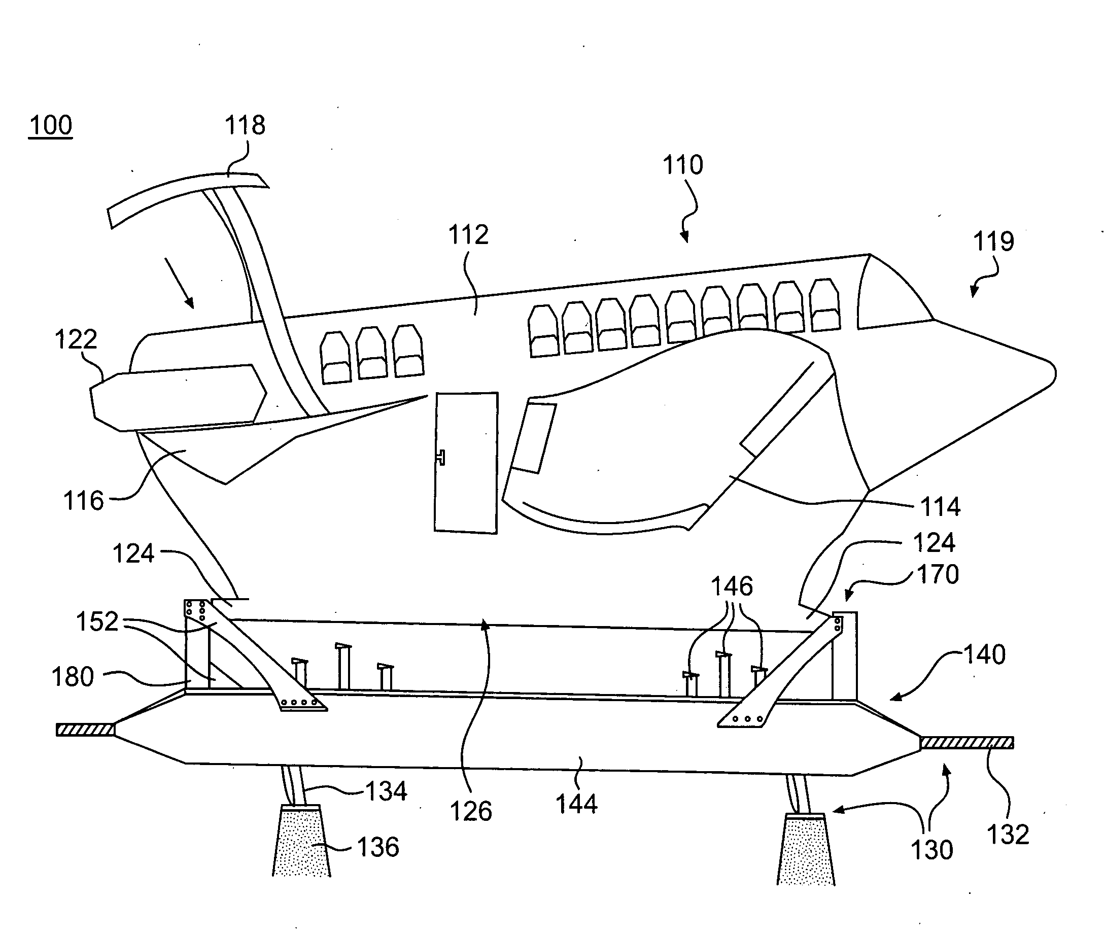
[0007]The shortcomings of the prior art can be overcome and additional advantages can be provided through exemplary embodiments of the present invention that are related to a transportation system that includes a vehicle body having a set of wings extending outward therefrom, a propulsion system, an elongated guide rail structure forming a path of travel, an undercarriage disposed beneath the vehicle body, a lifting gear mechanism coupling the vehicle body to the undercarriage, and a guidance assembly movably connecting the undercarriage to the guide rail structure. The set of wings are adapted to generate aerodynamic lift on the vehicle body when a traveling speed of the vehicle body exceeds a first speed. The propulsion system is configured to propel to vehicle body to accelerate the traveling speed of the vehicle body from less than the first speed to a second speed that exceeds the first speed. The lifting gear mechanism is configured to support a load of the vehicle body in a first position in relation to the undercarriage when the traveling speed of the vehicle body is ...

Problems solved by technology

More recently, however, as energy costs continue to increase, the use of rail transportation has been increasing throughout the U.S. Nevertheless, the conventional forms of mass transportation are generally reliant on oil-based fuels.
For example, buses are primarily powered by internal combustion engines that use gasoline or diesel, and conventional trains that cover long distances also operate through consumption of petroleum-based fuels.
Moreover, these conventional forms of mass transportation are inherently limited in speed by their designs and fundamental methods operation.

Method used


Image

  • Air bus transportation system
  • Air bus transportation system
  • Air bus transportation system

Examples


Embodiment Construction

[0019]While the specification concludes with claims defining the features of the invention that are regarded as novel, it is believed that the invention will be better understood from a consideration of the description of exemplary embodiments in conjunction with the drawings. It is of course to be understood that the embodiments described herein are merely exemplary of the invention, which can be embodied in various forms. Therefore, specific structural and functional details disclosed in relation to the exemplary embodiments described herein are not to be interpreted as limiting, but merely as a representative basis for teaching one skilled in the art to variously employ the present invention in virtually any appropriate form. For purposes of clarity, the same reference numbers will be used in the drawings to identify similar elements. Further, the terms and phrases used herein are not intended to be limiting but rather to provide an understandable description of the invention.

[00...


PUM


Abstract

A transportation system includes a vehicle having wings, a propulsion system, a lifting gear coupling the vehicle to an undercarriage, and a guidance assembly movably connecting the undercarriage to guide rails. The wings generate aerodynamic lift when the vehicle exceeds a first speed. The lifting gear supports a load of the vehicle in a first position in relation to the undercarriage when the vehicle travels at less than the first speed, allows the vehicle to lift to a second position in relation to the undercarriage as the vehicle accelerates beyond the first speed, and maintains the vehicle in the second position when the vehicle exceeds the first speed. The guidance assembly shiftingly engages the guide rails through rollers that are in rolling contact with the guide rails when the vehicle is in the first position and are displaced from the guide rails when the vehicle is in the second position.

Description

CLAIM OF PRIORITY[0001]This application claims the benefit of U.S. Provisional Application No. 61 / 213,540, filed on Jun. 18, 2009. The disclosure of the above-referenced application is incorporated herein by reference.FIELD OF THE INVENTION[0002]Exemplary embodiments of the present invention relate to transportation systems, and, more particularly, to transportation systems providing vehicles that attain aerodynamically airborne flight and achieve high-speeds while being guided along a path of travel provided by a guide rail structure.BACKGROUND OF THE INVENTION[0003]The statements in this section merely provide background information related to the present disclosure and may not constitute prior art.[0004]Transportation of people and cargo has become increasingly important in our modern lives. In the United States, the typical modes of travel between cities include air, bus, personal automobile, and, to a somewhat more limited extent, conventional rail. Following World War II, the ...

Claims


Application Information

Patent Timeline
IPC IPC(8): B61D15/00E01B25/00B60M1/02
CPCB60M7/00B61B5/02B64C37/00Y02T50/82E01B25/00Y02T30/30B64F1/10Y02T30/00Y02T50/80
Inventor SIMON, ABNER J.
Owner SIMON ABNER J
Learn More