Linear actuator and camera shake correction mechanism

a technology of actuator and camera, applied in the field of linear actuator, can solve the problems of difficult to obtain a strong thrust and inevitable decrease in the length of the coil, and achieve the effect of smooth movement with a high degree of thrust and suppression of the occurrence of thrust rippl

Inactive Publication Date: 2010-12-23
PENTAX RICOH IMAGING CO LTD
View PDF3 Cites 15 Cited by
  • Summary
  • Abstract
  • Description
  • Claims
  • Application Information

AI Technical Summary

Benefits of technology

[0009]The present invention is advantageous in that it provides at least one of a linear actuator and a camera shake correction mechanism configured to suppress occurrence of a ripple of a thrust and thereby to enhance the total thrust produced on a coil body of the linear actuator.
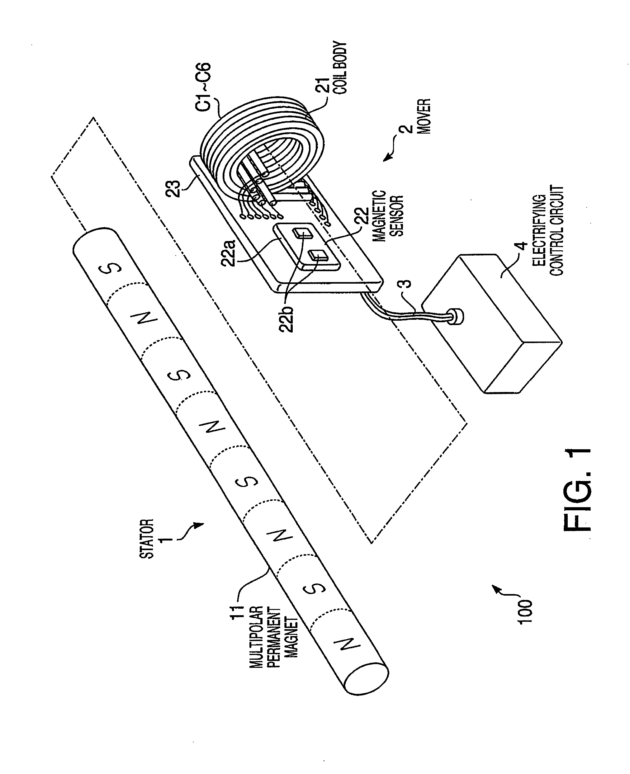
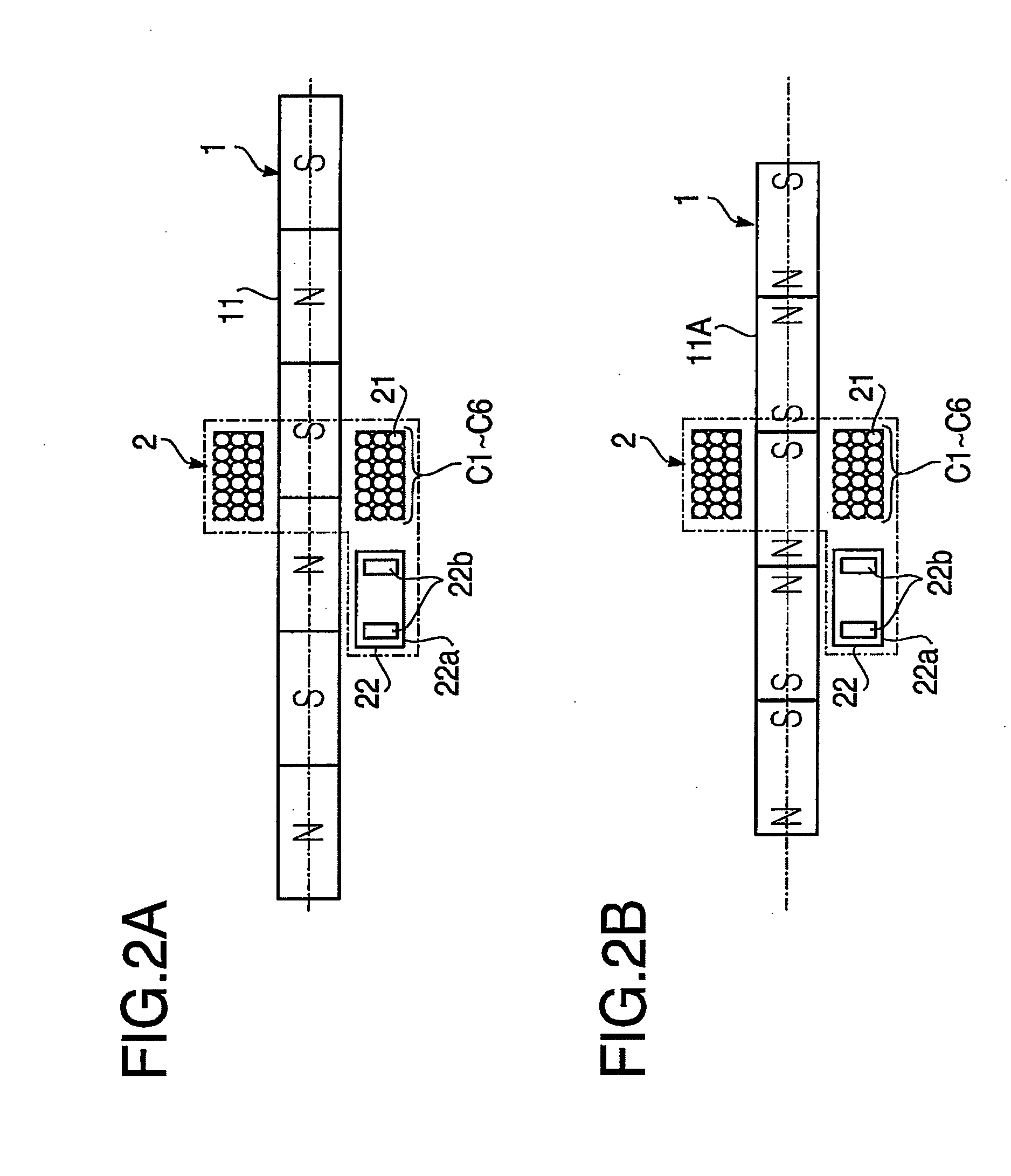
[0011]Such a configuration makes it possible to detect which of the S pole and N pole each of the coil units faces and thereby to switch the direction of the current supplied to each of the coil units in accordance with the detected position of each of the coil units. Consequently, it becomes possible to produce the thrust from all of the coil units forming the coil body, and thereby to suppress occurrence of a ripple of the thrust. Therefore, the linear actuator configured to be able to smoothly move with a high degree of thrust.

Problems solved by technology

For this reason, when the actuator is downsized, the length of the coil inevitably decreases, and thereby it becomes difficult to obtain a strong thrust.

Method used


Image

  • Linear actuator and camera shake correction mechanism
  • Linear actuator and camera shake correction mechanism
  • Linear actuator and camera shake correction mechanism

Examples


example

[0062]Hereafter, an example to which the above described linear actuator is applied is explained with reference to FIGS. 7A and 7B. FIG. 7A is a partial exploded perspective view of a camera having a camera shake correction mechanism to which the above described linear actuator is applied. As shown in FIG. 7A, the camera includes a shooting lens 101, an image pickup device 102 which picks up an image formed by the shooting lens 101, and a camera-shake correction mechanism 200 located between the shooting lens 101 and the image pickup device 102. The shooting lens 101 is supported by a lens frame 111, and a lens guide 112 is inserted into a part of the lens frame 111 so that the lens frame 111 is movable in a direction of an optical axis. Another part of the lens frame 111 is engaged with a lead screw 114 which is rotated by a step motor 113 fixed to a camera body (not shown). With this structure, the lens frame 111 (i.e., the shooting lens 101) is moved in the direction of the optic...


PUM


Abstract

A linear actuator including a multipolar magnet configured such that an S pole and an N pole are linearly aligned in an alternating manner, coil body having a plurality of separate coil units integrally arranged in a lengthwise direction of the coil body being provided to be movable relatively with respect to the multipolar magnet, a magnetic sensor that detects a position of the coil body along the lengthwise direction of the coil body with respect to the multipolar magnet, and an electrifying control circuit that individually controls currents to be supplied to the plurality of coil units based on the position of the coil body detected by the magnet sensor.

Description

BACKGROUND OF THE INVENTION[0001]The present invention relates to a linear actuator configured to produce a thrust for linear movement, and particularly to enhancement of the strength of the thrust of the linear actuator.[0002]The linear actuator, which is frequently called a linear motor, is configured to move one of a magnet and a coil by utilizing a thrust produced by electrifying the coil arranged in a magnetic field generated by the magnet. An example of a linear actuator is disclosed in Japanese Patent Provisional Publication No. 2007-282475A (hereafter, referred to as JP2007-282475A). In JP2007-282475A, it is disclosed that a mover is formed such that a plurality of permanent magnets are linearly arranged and an S pole and an N pole are alternately arranged in such a manner that that identical poles face with respect to each other, and that the coil serving as a stator is arranged in a magnetic field generated by the permanent magnets. In this configuration, by controlling a ...

Claims


Application Information

Patent Timeline
IPC IPC(8): G03B17/00H02K41/03G03B5/00H02P25/06H04N5/232
CPCG02B27/646G03B2205/0007H02K3/28H02K3/47H02K11/0021G03B2205/0069H02K41/03H02P6/006H02P25/06H04N5/23248H02K11/0073H02K11/215H02K11/33H04N23/68
Inventor KUROSAWA, YUICHI
Owner PENTAX RICOH IMAGING CO LTD
Why Eureka
Try Eureka