
Intrinsically safe video inspection system

a video inspection system and intrinsically safe technology, applied in the field of video cameras and inspection systems, can solve the problems of poor lighting, no conditions, no solution, etc., and achieve the effects of low power consumption, high 3.2 megapixel resolution, and light weight solution

Active Publication Date: 2010-12-23
POOL LEONARD
View PDF13 Cites 37 Cited by
  • Summary
  • Abstract
  • Description
  • Claims
  • Application Information

AI Technical Summary

Benefits of technology

[0014]The intrinsically safe camera system works in various hazardous environments, allowing users the ability to remotely view and inspect various mines, silos, and storage tanks. Because it is a low power solution and high 3.2 megapixel resolution, it can be used in other applications such as submersibles, surveillance, oil rigs, etc. The digital zoom capability allows for the close inspection and examination of specific areas with greater detail and provides a lighter weight solution than using an optical zoom. Utilizing an LED fiber light pipe for illumination needs, the video inspection system of the present invention provides for the illumination in various cavity sizes, while reducing the risk of unintended accidents.

Problems solved by technology

Due to the extreme conditions and the potential of loss or damage to persons and machines, these unique areas demand regular assessment; such as verification of content, corrosion, failures in the materials or construction and unwanted objects.
Additionally, these applications have restrictive conditions such as poor lighting, access, and a greater potential for hazardous or explosive gases and / or fluids.
There are other commercially available inspection systems yet none meet the conditions of certified “Intrinsically Safety is Type”.

Method used


Image

  • Intrinsically safe video inspection system
  • Intrinsically safe video inspection system
  • Intrinsically safe video inspection system

Examples


Embodiment Construction

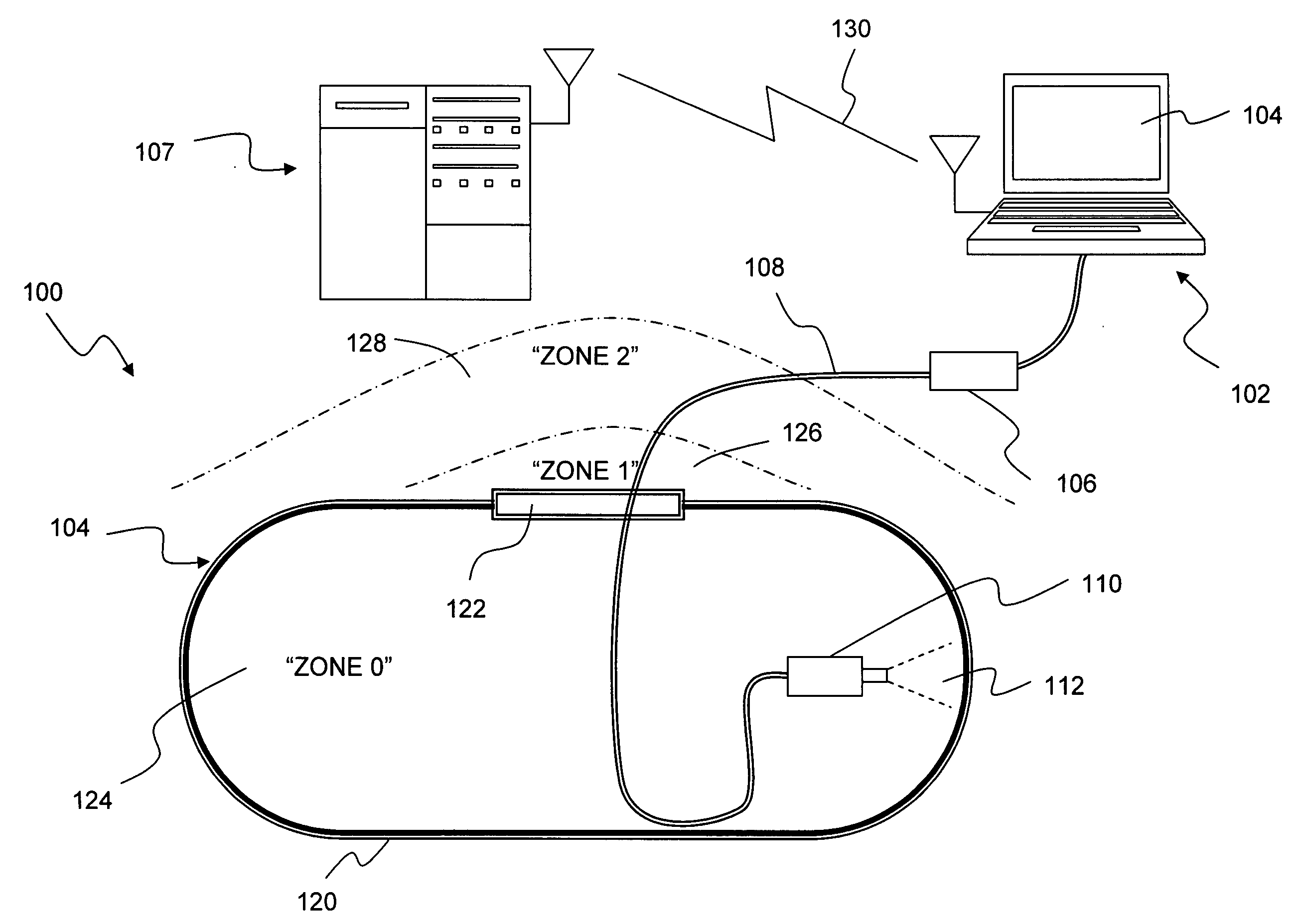
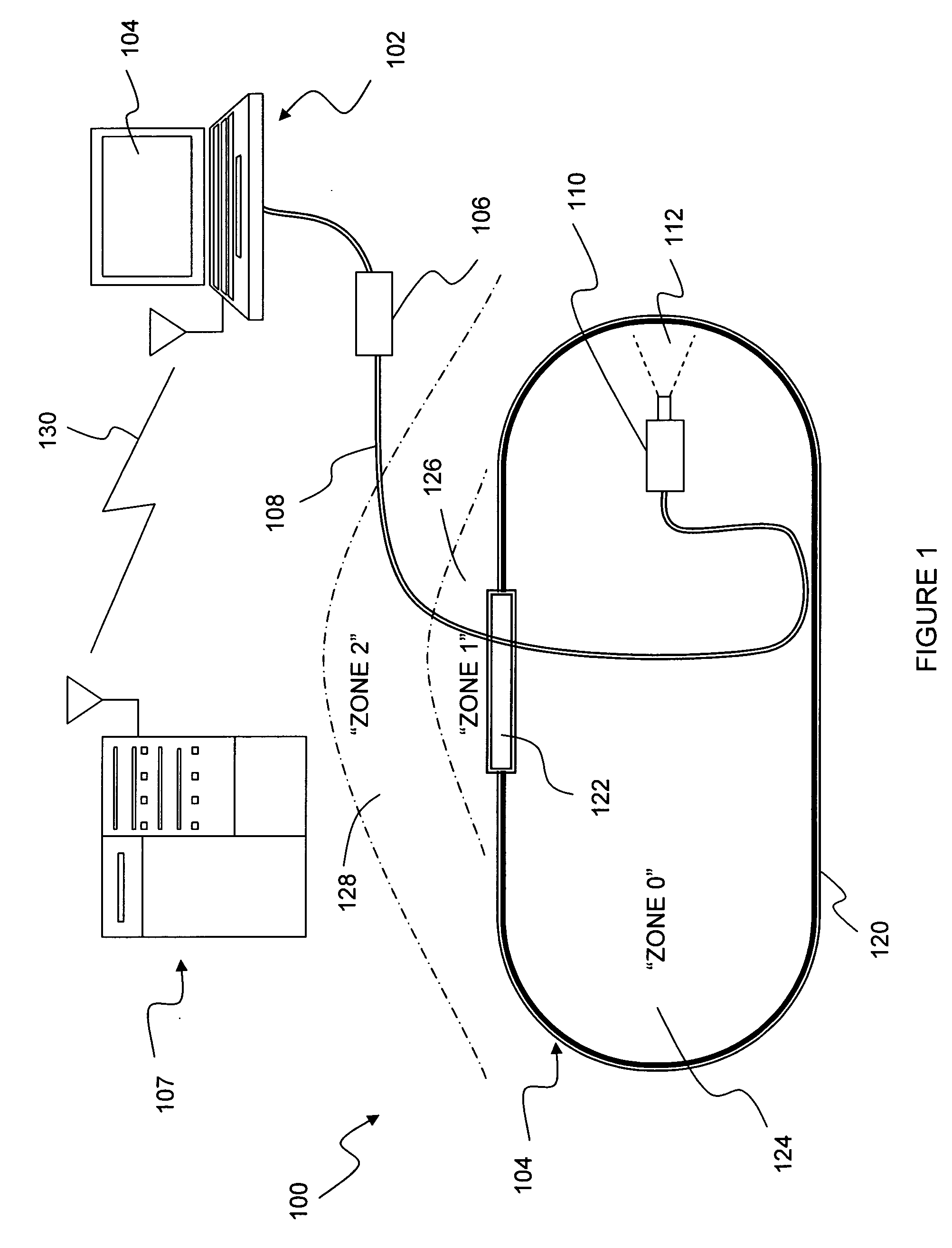
[0020]Referring initially to FIG. 1, a system level block diagram of the intrinsically safe camera system of the present invention is shown and generally designated 100. System 100 includes a host computer 102 or other video display device, a hazardous environment 104, a cable conditioning module 106 and an interconnecting cable 108 extending to the intrinsically safe camera assembly 110 having a video image area 112.

[0021]Hazardous environment 104 may, in some instances, include a chamber or tank 120 having an internal space 124 designated as Zone 0. This represents an extremely hazardous environment. Adjacent the opening of chamber 120 and opening 122 is a less hazardous area 126 designated as Zone 1, and a least hazardous area 128 designated Zone 2.

[0022]As shown in this Figure, cable 108 extends from the host computer or other video display device and cable conditioning module 106, through opening 122 and into Zone 0, 124. As can be appreciated, it is important that cable 108 be...


PUM


Abstract

An intrinsically safe video inspection system intended for use in a Class I, Zone 0 area is capable of visually surveying hazardous area locations; where the potential for fire or explosion exists because of gases, dust, or easily ignitable fibers in the atmosphere. The intrinsically safe camera of the present invention has the distinct ability to be used all areas that require increased safety and works in various hazardous environments, allowing users the ability to remotely view and inspect various mines, silos, and storage tanks. The inspection system includes a low power, high 3.2 megapixel resolution camera with digital zoom capability that allows for the close inspection and examination and utilizes an LED fiber light pipe for illumination needs. The video inspection system of the present invention provides for the illumination in various cavity sizes, while reducing the risk of unintended accidents.

Description

RELATED APPLICATIONS[0001]This application claims the benefit of priority to U.S. Provisional Patent Application Ser. No. 61 / 268,920 entitled “Intrinsically Safe Video Inspection System” filed Jun. 16, 2010, and currently co-pending.FIELD OF THE INVENTION[0002]The present invention relates generally to video cameras and inspection systems which include video cameras. The present invention is particularly, though not exclusively, related to video inspection systems for use in hazardous environments and especially those hazardous environments having a volatile vapors with a high risk of fire or explosion.BACKGROUND OF THE INVENTION[0003]With the technological advances that have been made in camera technology, including the development of miniature and solid state digital cameras, it has been increasingly commonplace to incorporate video cameras into ordinary diagnostic equipment. One specific application of the modern cameras is in the field of robotics, and remote inspection systems....

Claims


Application Information

Patent Timeline
Patent Type & Authority Applications(United States)
IPC IPC(8): H04N7/18
CPCH04N5/2256H04N2005/2255H04N7/183G02B23/2492G02B23/26H04N23/555H04N23/56H04N23/651G06T7/0004H04N7/22
Inventor POOL, LEONARD
Owner POOL LEONARD
Learn More