Image Processing Method and Associated Apparatus for Rendering Three-dimensional Effect Using Two-dimensional Image

a two-dimensional image and image processing technology, applied in the field of three-dimensional (3d) effect rendering, can solve the problems of inability to fully understand the depth of the image, burdened with more complicated and costly implementation, and inability to achieve depth information, etc., to achieve the effect of enhancing the overall system performance and reducing software and hardware costs

Active Publication Date: 2010-12-23
MEDIATEK INC
View PDF5 Cites 4 Cited by
  • Summary
  • Abstract
  • Description
  • Claims
  • Application Information

AI Technical Summary

Benefits of technology

[0004]Therefore, it is an objective of the invention to provide an image processing method and an associated apparatus for rendering a 3D effect using 2D images, so as to overcome complications involved in the 3D image rendering approach to reduce software and hardware costs as well as enhancing an overall system performance.
[0005]The present invention provides an image processing method for rendering a 3D effect by transforming a first quadrilateral image to a second quadrilateral image. The image processing method comprises: providing the first quadrilateral image; generating an outline associated with the second quadrilateral image according to the first quadrilateral image and the 3D effect; dividing an area within the outline into a plurality of second blocks, and correspondingly determining a plurality of first blocks from first quadrilateral image; scaling image data of the first bloc...

Problems solved by technology

The 2D image rendering approach is easier and less expensive to implement, yet has a disadvantage of lacking depth information.
The 3D image rendering approach, although having an advantage of being capable of rendering better visual enjoyment to viewers using its depth information, is burdened with more complicated and more costly implementation.
More specifically, when the 3D ...

Method used


Image

  • Image Processing Method and Associated Apparatus for Rendering Three-dimensional Effect Using Two-dimensional Image
  • Image Processing Method and Associated Apparatus for Rendering Three-dimensional Effect Using Two-dimensional Image
  • Image Processing Method and Associated Apparatus for Rendering Three-dimensional Effect Using Two-dimensional Image

Examples


first embodiment

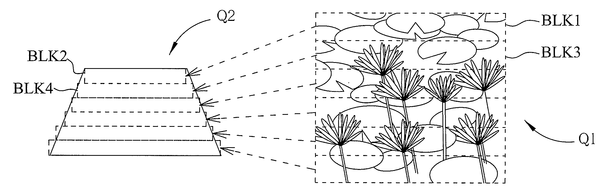
[0023]With reference to FIG. 4, the block determining unit 202 calculates change rates of coordinates at two sides of the trapezoidal image Q2 (i.e., the change rates of the planar coordinates P21 and P23 of the two left vertices, and the change rates of the planar coordinates P22 and P24 of the two right vertices of the quadrilateral image Q2) to respectively obtain a first coordinate change rate and a second coordinate change rate. With the first and second coordinate change rates, coordinates of two terminal points of each scan line of the trapezoidal image can be obtained. Modifications may be made to the foregoing approaches of dividing the quadrilateral image Q2 into the plurality of blocks and determining from the quadrilateral image Q1 the plurality of blocks corresponding to the blocks of the quadrilateral image Q2. For example, in the first embodiment, the quadrilateral image Q2 is divided into a plurality of rectangular blocks in a unit of one scan line, and the block det...

second embodiment

[0025]Further, in the second embodiment, the area of each rectangular block of the quadrilateral image Q2 determined by the block determining unit 202 is covered by a single scan line; however, the corresponding rectangular blocks of the quadrilateral image Q1 may be an area covered by a plurality of scan lines, and the graphic unit 203 respectively scales images of a plurality of scan lines in the quadrilateral image Q1 to generate an image corresponding to the scan lines in the quadrilateral image Q2. FIGS. 7A and 7B are schematic diagrams illustrating a corresponding relationship of a block between the quadrilateral images Q1 and Q2 determined by the block determining unit. As shown in FIG. 7A, rectangular blocks in the quadrilateral image Q1 are equal in size, and respectively correspond to a horizontal scan line of the quadrilateral image Q2, as indicated by dotted arrows. Image data of each rectangular block in the quadrilateral image Q1 is scaled by the graphic unit 203 to ge...

third embodiment

[0026]To further enhance image quality, according to the invention, apart from defining the rectangular blocks in the quadrilateral image Q1 to cover an area of a single scan line or a plurality of scan lines, the rectangular blocks may have different sizes from one another. FIGS. 8A and 8B are schematic diagrams illustrating corresponding relationships between differently sized rectangular blocks of the quadrilateral image Q1 and same sized rectangular blocks of the quadrilateral image Q2 divided by the block determining unit 202. As shown in the diagrams, narrower regions or smaller blocks in the quadrilateral image Q2 correspond to larger rectangular blocks in the quadrilateral image Q1, meaning that areas of corresponding blocks of the quadrilateral images Q1 and Q2 show an inverse non-linear relationship.

[0027]In the third embodiment, the block determining unit 202 calculates an area and planar coordinates of each rectangular block of the quadrilateral image Q1 with reference t...


PUM


Abstract

An image processing apparatus is for rendering a three-dimensional (3D) effect by transforming a first quadrilateral image to a second quadrilateral image. The apparatus includes a target image determining unit, a block determining unit and a graphic unit. The target image determining unit generates an outline associated with the second quadrilateral image according to the first quadrilateral image and the 3D effect. The block determining unit divides an area within the outline into a plurality of second blocks and correspondingly determines a plurality of first blocks from the first quadrilateral image. The graphic unit scales image data of the first blocks to respectively generate image data of the second blocks to obtain the second quadrilateral image.

Description

CROSS REFERENCE TO RELATED PATENT APPLICATION[0001]This patent application claims the benefit of a U.S. provisional patent application No. 61 / 218,077 filed on Jun. 18, 2009, which is incorporated herein by reference in its entirety.FIELD OF THE INVENTION[0002]The present invention relates to a mechanism for rendering a three-dimensional (3D) effect, and more particularly, to an image processing method and an associated apparatus for rending a 3D effect using two-dimensional (2D) images.BACKGROUND OF THE INVENTION[0003]In a current user interface system, e.g., a user interface of a portable device like a mobile phone, methods for rendering graphics or images include a 2D image rendering approach and a 3D image rendering approach. The 2D image rendering approach is easier and less expensive to implement, yet has a disadvantage of lacking depth information. The 3D image rendering approach, although having an advantage of being capable of rendering better visual enjoyment to viewers usi...

Claims


Application Information

Patent Timeline
IPC IPC(8): G06T15/00
CPCG06T15/20G06T13/80
Inventor LEE, RUEN-RONEWANG, TSAI-SHENGTAI, CHIA-LIANG
Owner MEDIATEK INC
Why Eureka
Try Eureka