
Radio Frequency Identification Reader/Writer and a Method for Implementing Antenna Switching

Inactive Publication Date: 2010-12-23
SIEMENS AG
View PDF2 Cites 14 Cited by
  • Summary
  • Abstract
  • Description
  • Claims
  • Application Information

AI Technical Summary

Benefits of technology

[0008]The present invention on the one hand provides an RFID reader / writer, and on the other hand provides a method for implementing antenna switching of the RFID reader / writer, so as to expand the coverage area of the RFID reader / writer.
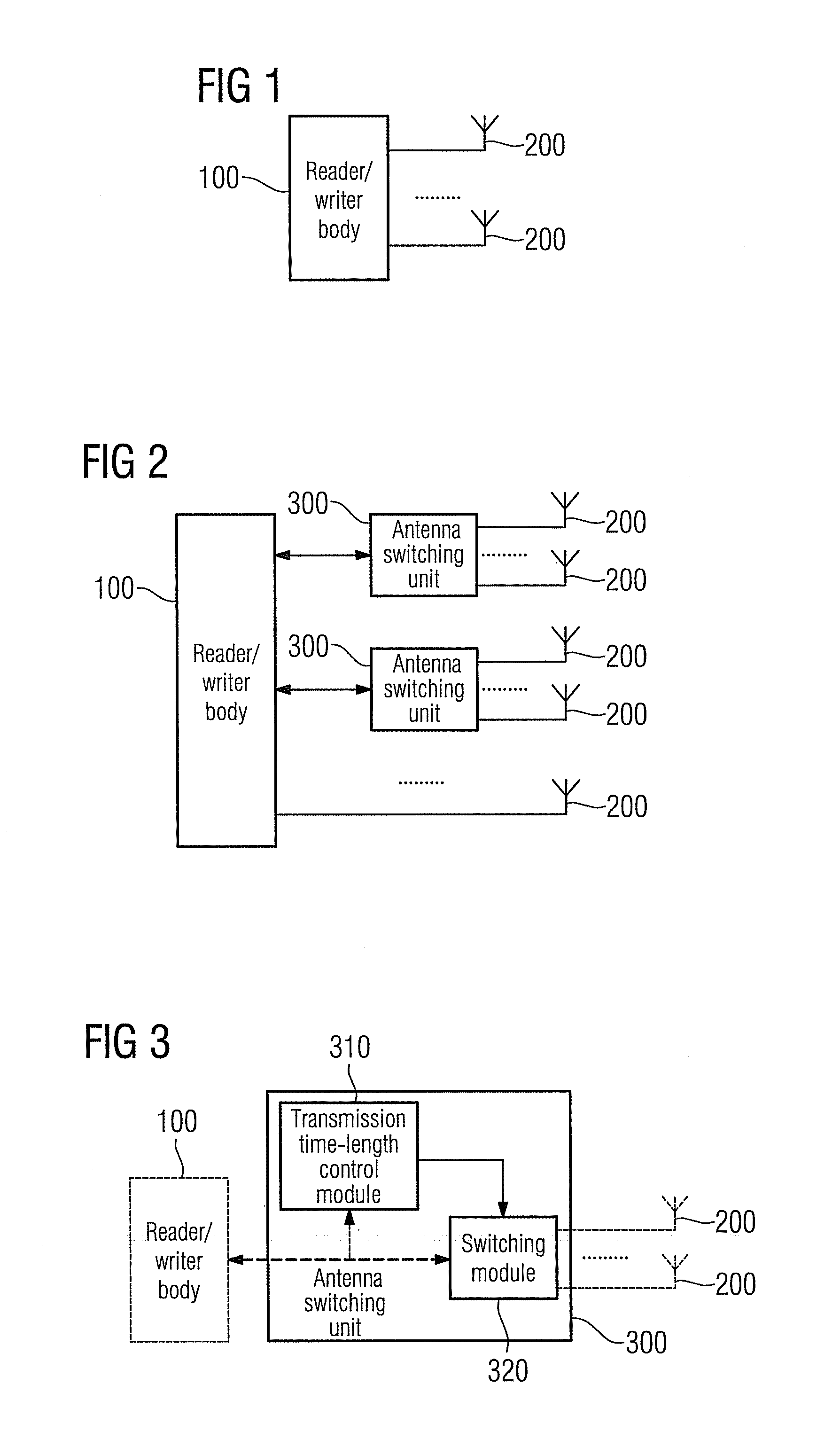
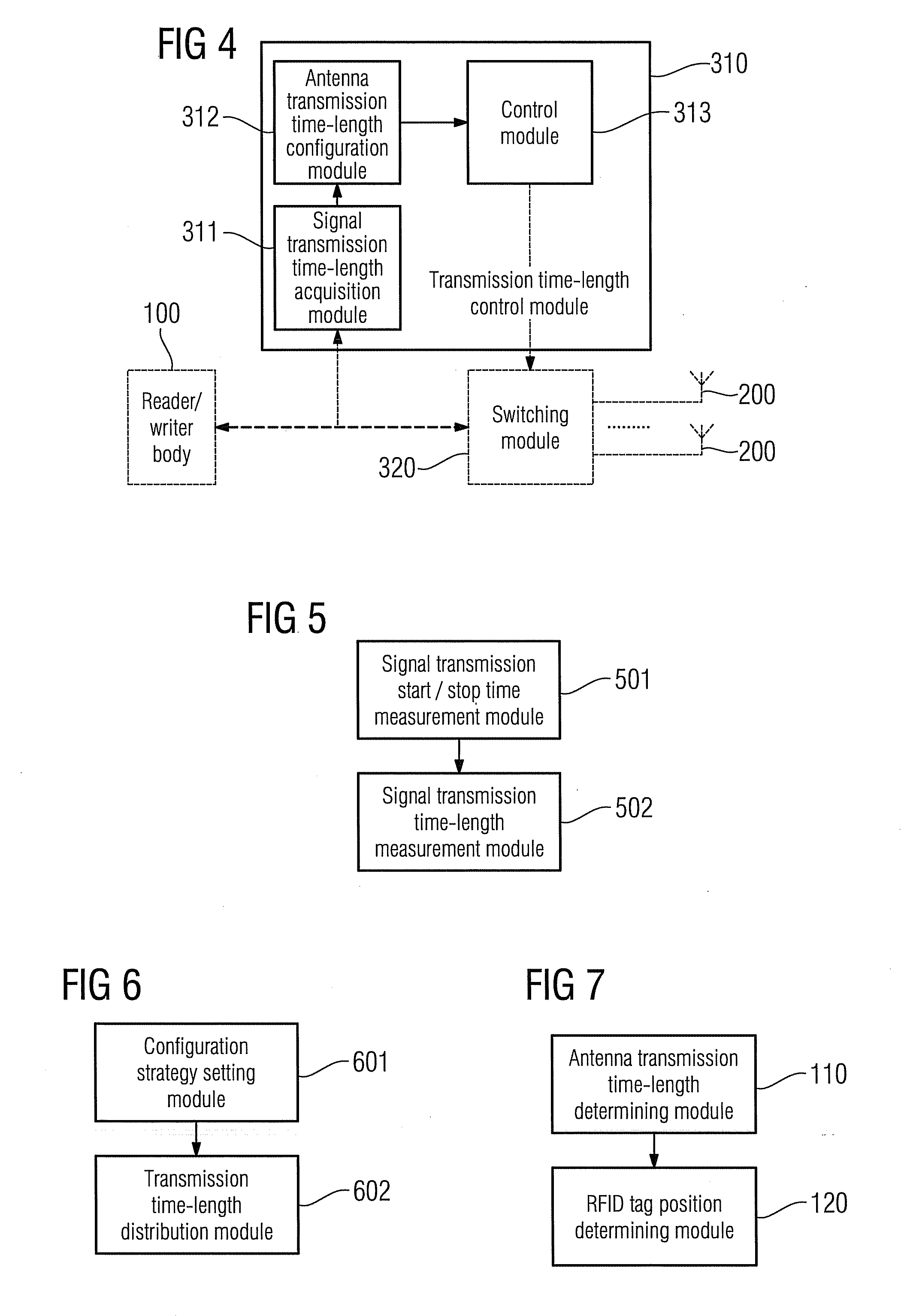
[0025]It can be seen from the above technical solution that, in the present invention by setting at least one antenna switching unit between the reader / writer body and the antennas, with one end of each of the antenna switching units being connected to one port of the reader / writer body, while the other end thereof is connected to at least two antennas, it increases the number of antennas corresponding to a port, so under working conditions, each of the antenna switching units acquires the length of sustained time for the signal transmission distributed to the port connected to the antenna switching unit by the reader / writer body; the time-length for the signal transmission and sequence thereof of each of the antennas connected thereto are configured according to the length of sustained time for the signal transmission, and a switching control is performed on the signal transmission of each of the antennas connected to the antenna switching unit according to the acquired configuration result for the signal transmission; therefore there is no need to change the transmitting power distributed to each of the antennas, and the coverage area of the RFID reader / writer is expanded.

Problems solved by technology

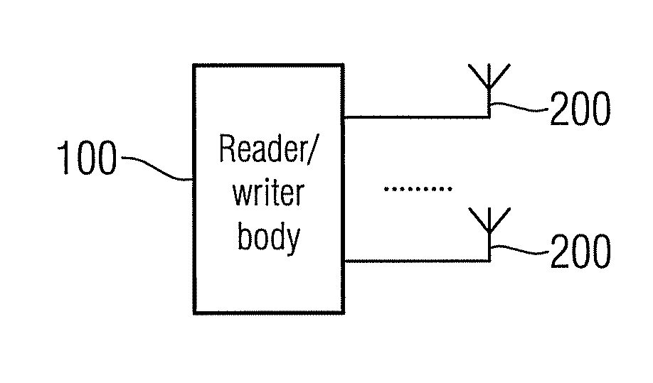
However, in many cases, due to the transmitting power limitation of antennas 200 of the RFID reader / writer and the limitation in the number of antennas 200 supported in the RFID system in the prior art, the coverage area of the RFID reader / writer cannot satisfy the performance requirements of the RFID system.

Method used


Image

  • Radio Frequency Identification Reader/Writer and a Method for Implementing Antenna Switching
  • Radio Frequency Identification Reader/Writer and a Method for Implementing Antenna Switching
  • Radio Frequency Identification Reader/Writer and a Method for Implementing Antenna Switching

Examples


example one

[0106]FIG. 10 is a structural diagram of the RFID reader / writer in example one of the present invention. As shown in FIG. 10, in this example, assume that the reader / writer body has four ports, from port 1 to port 4, and an antenna switching unit is fitted to each port, and each of the antenna switching units corresponds to two antennas; and assume that each of the antennas is separately labeled as antenna 1 to antenna 8 as shown in FIG. 10, then port 1 corresponds to antenna 1 and antenna 2, port 2 corresponds to antenna 3 and antenna 4, port 3 corresponds to antenna 5 and antenna 6, and port 4 corresponds to antenna 7 and antenna 8.

[0107]Further, assume that a configuration strategy for the signal transmission which is for equal distribution is set in advance in the reader / writer body and each of the antenna switching units, and assume the length of sustained time for the signal transmission distributed to each port by the reader / writer body is T.

[0108]When in practical operation,...

example two

[0112]In example two of the present invention, the structural diagram of the RFID reader / writer shown in FIG. 10 is still taken by way of example. In this example, assume a configuration strategy for the signal transmission by polling distribution is set in advance in the reader / writer body and each of the antenna switching units, and assume the length of sustained time for the signal transmission distributed to each port by the reader / writer body is T.

[0113]When in practical operation, the antenna switching unit first measures the power level of the signal passing through the port of the reader / writer body connected to the antenna switching unit, and compares the obtained measurement result with a preset transmitting power level threshold; when it reaches the preset transmitting power level threshold, the initial time of reaching signal transmission is determined, and the length of sustained time of the power level of reaching the preset transmitting power level threshold is record...


PUM


Abstract

An RFID reader / writer including a reader / writer body, antennas and an antenna switching unit is provided. The reader / writer body distributes to each of its own ports a length of sustained time for transmitting a signal. One end of the antenna switching unit is connected to one port of the reader / writer body, while the other end is connected to two antennas. The antenna switching unit acquires a length of sustained time for the signal transmission distributed to the port by the reader / writer body, configures the time-length for the signal transmission and the sequence thereof of the two antennas according to the length of sustained time for the signal transmission, obtains a configuration result for signal transmission, and performs a switching control on the signal transmission of the two antennas according to the signal transmission configuration result. Further, an implementation method for the antenna switching of the RFID reader / writer is described.

Description

CROSS REFERENCE TO RELATED APPLICATIONS[0001]This application is the US National Stage of International Application No. PCT / EP2008 / 060116 filed Aug. 1, 2008 and claims the benefit thereof. The International Application claims the benefits of Chinese Application No. 200710162984.3 CN filed Oct. 9, 2007; both of the applications are incorporated by reference herein in their entirety.FIELD OF INVENTION[0002]The present invention relates to radio frequency identification (RFID) technology, in particular to an RFID reader / writer and a method for implementing antenna switching.BACKGROUND OF INVENTION[0003]RFID is an automatic identification technology which comprises: bar code recognition, optical character recognition, smart card recognition, biometric identification and so on. In an RFID system, it mainly comprises an RFID tag and an RFID reader / writer.[0004]FIG. 1 is a structural diagram of an RFID reader / writer according to the prior art. As shown in FIG. 1, the RFID reader / writer com...

Claims


Application Information

Patent Timeline
IPC IPC(8): H04Q5/22
CPCG06K7/0008H01Q3/24H01Q1/2216G06K7/10346
Inventor HORST, DIETERLAMPE, MATTIASLI, HUIYU, DANYUAN, YONGZHANG, LIANG
Owner SIEMENS AG
Learn More