
Method and apparatus for controlling power supply of audio amplifier

a technology of audio amplifiers and power supply, applied in the direction of amplifiers with semiconductor devices only, dc amplifiers with modulators and demodulators, amplifiers with semiconductor devices/discharge tubes, etc., can solve problems such as device heating or noise generation in neighboring electronic devices

Active Publication Date: 2010-12-23
SAMSUNG ELECTRONICS CO LTD
View PDF6 Cites 14 Cited by
  • Summary
  • Abstract
  • Description
  • Claims
  • Application Information

AI Technical Summary

Benefits of technology

The present invention provides a method and apparatus for controlling the power supply voltage of an audio amplifier based on the input audio signal level. This allows for more efficient and accurate control of the amplifier's power supply, resulting in improved audio quality and reliability. The method includes estimating the audio output level based on correlations between the input audio signal level and audio level change factors, setting a power control value based on the estimated audio output level, and amplifying the audio output signal by variably controlling the power supply voltage according to the set power control value. The apparatus includes a digital signal processor for estimating the audio output level, setting the power control value, and a variable power supply unit for supplying the variable voltage to the power switching circuit unit. The technical effects of this invention include improved audio quality, reliability, and efficiency of audio amplifiers.

Problems solved by technology

The class-D audio amplifier that operates at high power may cause device heating or generate noise in neighboring electronic devices.

Method used


Image

  • Method and apparatus for controlling power supply of audio amplifier
  • Method and apparatus for controlling power supply of audio amplifier
  • Method and apparatus for controlling power supply of audio amplifier

Examples


Embodiment Construction

[0024]Hereinafter, the present invention will be described in detail by explaining exemplary embodiments of the present invention with reference to the attached drawings. The present invention may be embodied in various forms without being limited to the embodiments set forth herein. Descriptions of well-known parts are omitted for clarity, and like reference numerals refer to like elements throughout.

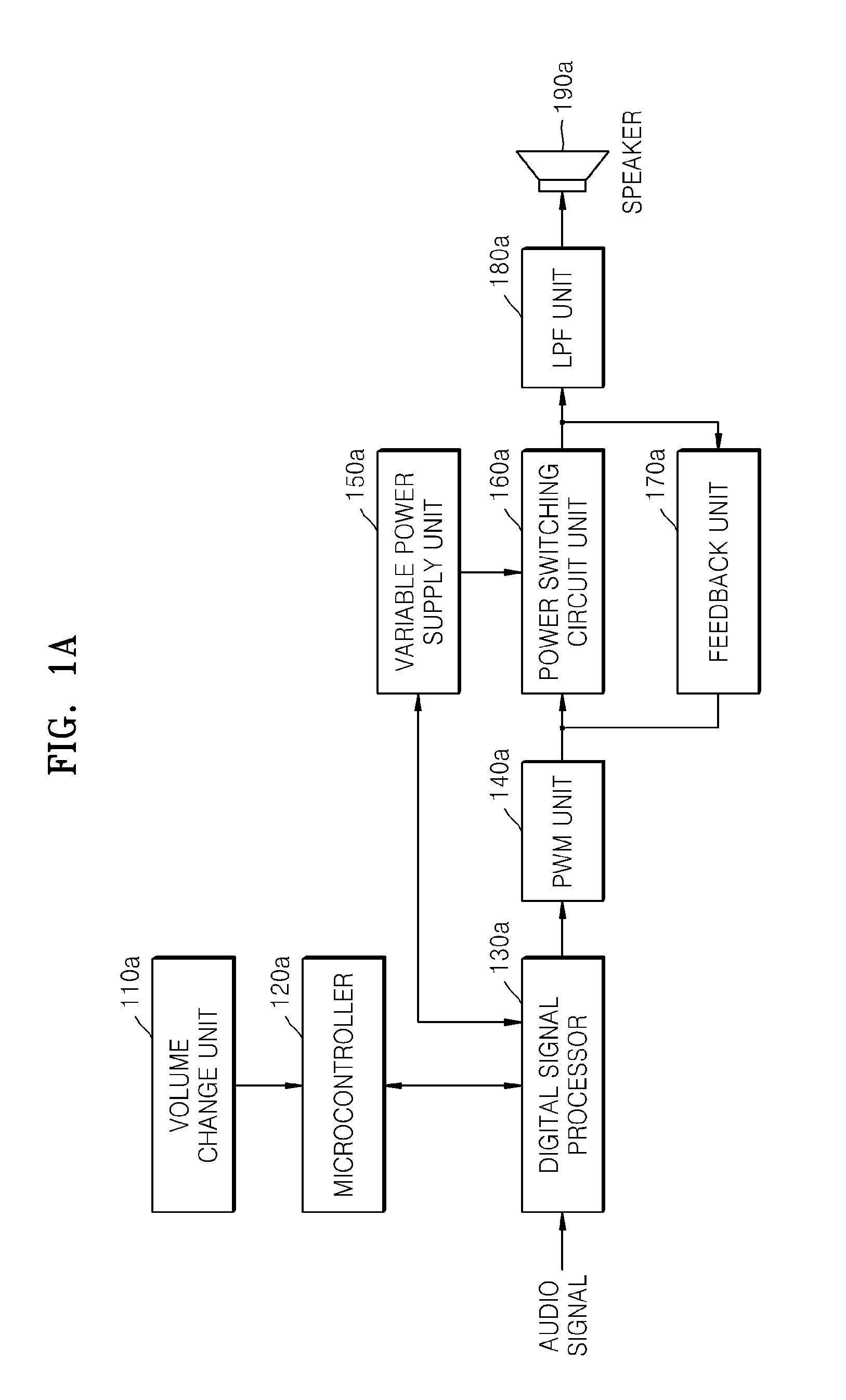
[0025]FIG. 1A is a block diagram of a closed-loop type class-D audio amplifier system according to an exemplary embodiment of the present invention.

[0026]Referring to FIG. 1A, when power supply voltage is changed, the closed-loop type class-D audio amplifier system simultaneously changes the duty and the amplitude of a pulse width modulation (PWM) signal supplied by the PWM unit 140a. Thus, an audio output of the closed-loop type class-D audio amplifier system is not affected by a power supply voltage change.

[0027]The closed-loop type class-D audio amplifier system includes a volume ch...


PUM


Abstract

A method of controlling power supply voltage of an audio amplifier delays an input audio signal; estimates, with a digital signal processor, an audio output level of the delayed input audio signal based on correlations between the delayed input audio signal level and audio level change factors; sets a value of power supply voltage supplied to a power switching circuit unit in correspondence with the estimated audio output level prior to outputting the delayed input audio signal on which the estimated audio output level is based; and amplifies the delayed audio input signal to provide an audio output signal by variably controlling the power supply voltage supplied to the power switching circuit unit according to the set value of power supply voltage.

Description

CROSS-REFERENCE TO RELATED PATENT APPLICATION[0001]This application claims priority from Korean Patent Application No. 10-2009-0054789, filed on Jun. 19, 2009, and Korean Patent Application No. 10-2009-0081982, filed on Sep. 1, 2009, in the Korean Intellectual Property Office, the disclosures of both of which are incorporated herein in their entirety by reference.BACKGROUND OF THE INVENTION[0002]1. Field of the Invention[0003]Apparatuses and methods consistent with the present invention relate to a digital audio amplifier system, and more particularly, to a method and apparatus for controlling a power supply of an audio amplifier by changing the power supply voltage supplied to a power switching circuit unit of the audio amplifier.[0004]2. Description of the Related Art[0005]In general, digital audio systems use audio amplifiers, which are classified into class-A, class-B, class-AB, and class-D audio amplifiers. Class-D audio amplifiers may prevent amplification efficiency reduction...

Claims


Application Information

Patent Timeline
Patent Type & Authority Applications(United States)
IPC IPC(8): H03F3/04
CPCH03F1/0222H03F1/025H03F3/217H03F2200/511H03F2200/351H03F2200/507H03F2200/03
Inventor KIM, HAN-KIPARK, HAE-KWANG
Owner SAMSUNG ELECTRONICS CO LTD
Learn More