Receiving apparatus, receiving method and communication system

a technology of receiving apparatus and receiving method, applied in the field of receiving apparatus, receiving method and communication system, can solve the problems of degrading reception performance and a large amount of computing operation, so as to improve the accuracy of bit log likelihood ratio, improve reception performance, and reduce the amount of computing operation

Active Publication Date: 2010-12-16
TOKYO INST OF TECH +1
View PDF2 Cites 9 Cited by
  • Summary
  • Abstract
  • Description
  • Claims
  • Application Information

AI Technical Summary

Benefits of technology

[0043]According to the present invention, since the transmitted signal candidate that produces the minimum metric among the metrics of the transmitted signal candidates is determined as the maximum likelihood sequence, and the bit log likelihood ratio of the maximum likelihood sequence are calculated, it is possible to perform soft-decision error correction decoding and hence improve reception performance.
[0044]Since the search direction generator calculates the direction that indicates noise enhancement, based on the weight coefficient calculated from the channel-estimated value, especially based on the Power method and/or the gradient of the metric obtained as the result of the hard-decision of the initial signal, it is possible to sharply reduce the amount of computing operation compared to the conventional MLD, and it is hence possible to pick up candidates that are close to the actual transmitted signal.
[0045]Since the likelihood processor determines the bit log likelihood ratio, by further taking the bit log likelihood ratio output from the decoder into consideration, it is possible to improve the ...

Problems solved by technology

In this way, since in MLD, as many metrics as the number of all the transmitted signal candidates are calculated, it is possible to obtain the optimal performance, but this method poses a problem that the amount of computi...

Method used


Image

  • Receiving apparatus, receiving method and communication system
  • Receiving apparatus, receiving method and communication system
  • Receiving apparatus, receiving method and communication system

Examples


embodiment 1

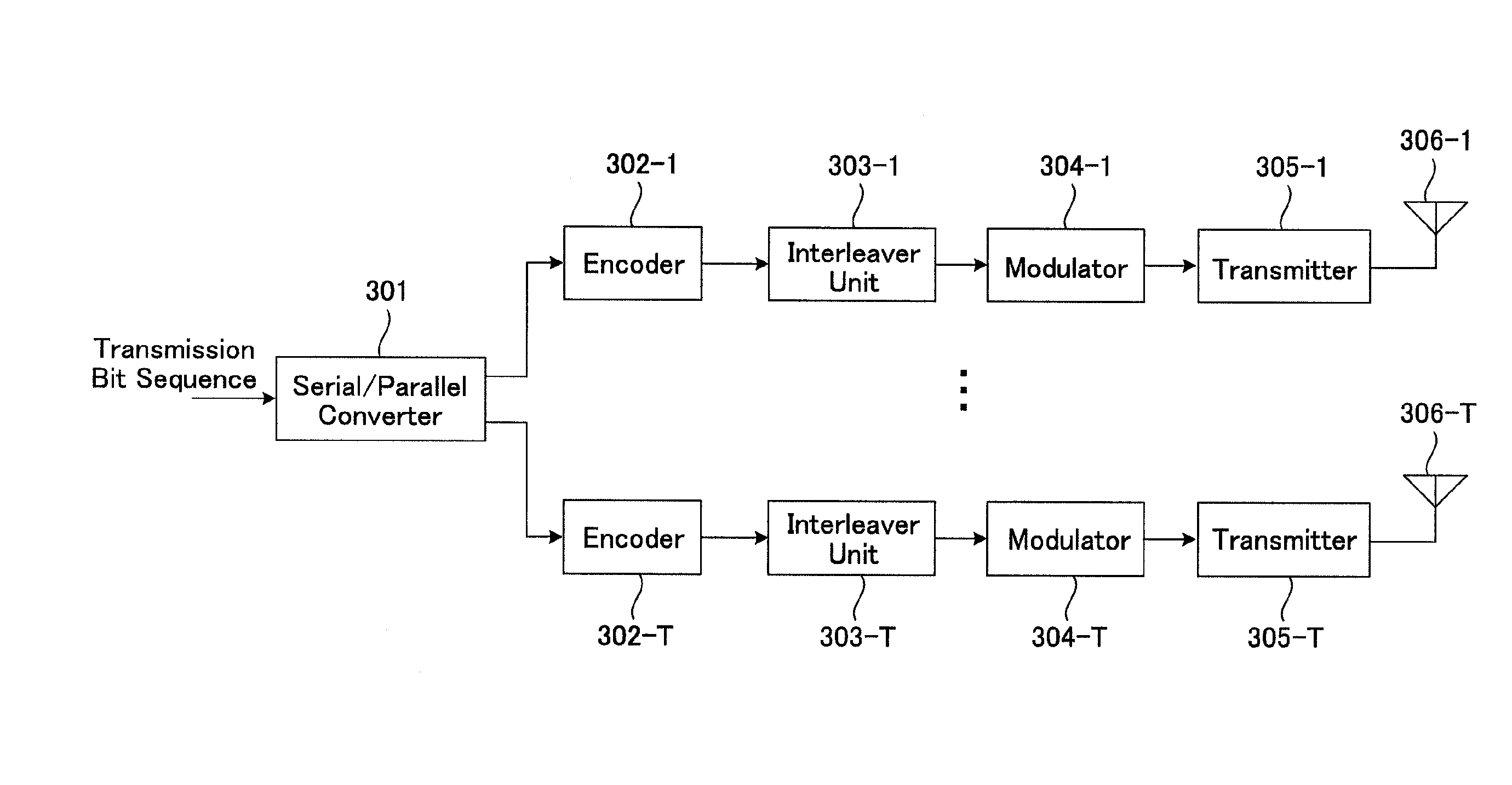
[0138]FIG. 1 is a block diagram showing a configuration of a transmitting apparatus in the first embodiment. The transmitting apparatus includes a serial-to-parallel converter 301, encoders 302-1 to 302-T, interleaver units 303-1 to 303-T, modulators 304-1 to 304-T, transmitters 305-1 to 305-T and transmitting antennas 306-1 to 306-T. A transmission bit sequence is serial-to-parallel converted by serial-to-parallel converter 301 so as to be divided into T bit sequences. The bit sequences are error correction coded by corresponding encoders 302-1 to 302-T, respectively, using, for example, convolution coding, turbo coding, LDPC (Low Density Parity Check) coding, or the like, and formed into encoded bit sequences. The encoded bit sequences are interleaved by interleavers 303-1 to 303-T, respectively. The encoded bit sequences after interleaving are mapped on modulation symbols such as QPSK (Quadrature Phase Shift Keying), 16QAM (Quadrature Amplitude Modulation) or the like, by modulat...

embodiment 2

[0163]In the first embodiment, the method of calculating bit LLRs when combined with error correction was illustrated. However, when the optimal bit LLR is determined, the minimum metric among inverted bit sequences is needed so that computing operation as much as that of MLD is required. When MLD with transmitted signal candidates reduced in number is used, if any inverted bit sequence remains in the candidates, it is possible to use the minimum metric of the remaining inverted bit sequence in calculating bit LLRs. However, in the first embodiment, concerning transmitted signal candidates, the transmitted signal candidates were searched out in order to determine the maximum likelihood sequence. However, in this case, there is a possibility that no inverted bit sequence will remain in the transmitted signal candidates, and if this case happens, it is impossible to calculate any bit LLR. In the second embodiment, a narrowing down method of transmitted signal candidates will be descri...

embodiment 3

[0173]In the third embodiment, a method of calculating bit LLRs in a simplified manner, using a step size will be described.

[0174]Described in the third embodiment is a method of calculating bit LLRs by determining inverted bit sequences of which the metric needs to be generated, using the step size generated in the first embodiment, and generating the metrics of the determined inverted bit sequences.

[0175]FIG. 7 is a block diagram showing a configuration of a signal detector 403 in the third embodiment. The difference from the signal detector 403 in the second embodiment is that a step size is output from updating value processor 604 to likelihood processor 606. First, likelihood processor 606 selects the transmitted signal candidate producing the minimum metric and determines the metric of the inverted bits of the selected transmitted signal candidate by considering the step size. Therefore, updating value processor 604 and likelihood processor 606 will be mainly described herein....


PUM


Abstract

To obtain excellent reception performance whilst cutting down the amount of computing operation in a MIMO communication system using soft-decision error correction coding. Received waves picked up by receiving antennas 401-1 to 401-R are converted from the radio frequency to the baseband signal by respective receivers 402-1 to 402-R to be output as a received signal. A signal detector 403 calculates bit LLRs of the transmitted signal based on the received signal and the channel-estimated values obtained from a channel estimator 404. The bit LLRs output from signal detector 403 are rearranged by deinterleaver units 405-1 to 405-T in the patterns opposite to the patterns in which interleaving was performed on the transmission side. The bit LLRs after de-interleaving are subjected to an error correction decoding process through decoders 406-1 to 406-T. The bit sequences after decoding are parallel-to-serial converted by a parallel-to-serial converter 407 so that the detected transmission bit sequence is output.

Description

TECHNICAL FIELD[0001]The present invention relates to a receiving apparatus, receiving method and communication system for performing communication in a MIMO system.BACKGROUND ART[0002]In radio communications such as mobile telephony system and the like, as a technology for enhancing the transmission speed without widening the frequency bandwidth, MIMO (Multiple Input Multiple Output) transmission for performing spatial multiplexing transmission using a plurality of transmitting and receiving antennas has been known.[0003]FIG. 18 is a block diagram showing a configuration of a transmitting apparatus for MIMO transmission. The transmitting apparatus includes a serial-to-parallel converter 5001, modulators 5002-1 to 5002-T, transmitters 5003-1 to 5003-T and transmitting antennas 5004-1 to 5004-T.[0004]To begin with, a transmission bit sequence is serial-to-parallel converted by serial-to-parallel converter 5001 so as to be divided into T bit sequences. The bit sequences are mapped on ...

Claims


Application Information

Patent Timeline
IPC IPC(8): H04L27/28
CPCH04L25/03171H04L2025/03426
Inventor FUKAWA, KAZUHIKOSUZUKISUYAMA, SATOSHIYAMADA, RYUTAOKAMOTO, NAOKI
Owner TOKYO INST OF TECH
Why Eureka
Try Eureka