
Variable transmittance optical filter and uses thereof

a transmittance optical filter and variable technology, applied in the field of variable transmittance optical filters, can solve the problems of slow reversal of photochromics from dark to light state, inability to control manually, and inability to achieve achieving the effect of reducing the cost of optical filters, and improving the efficiency of optical filters

Active Publication Date: 2010-12-16
SOLUTIA CANADA INC
View PDF13 Cites 252 Cited by
  • Summary
  • Abstract
  • Description
  • Claims
  • Application Information

AI Technical Summary

Benefits of technology

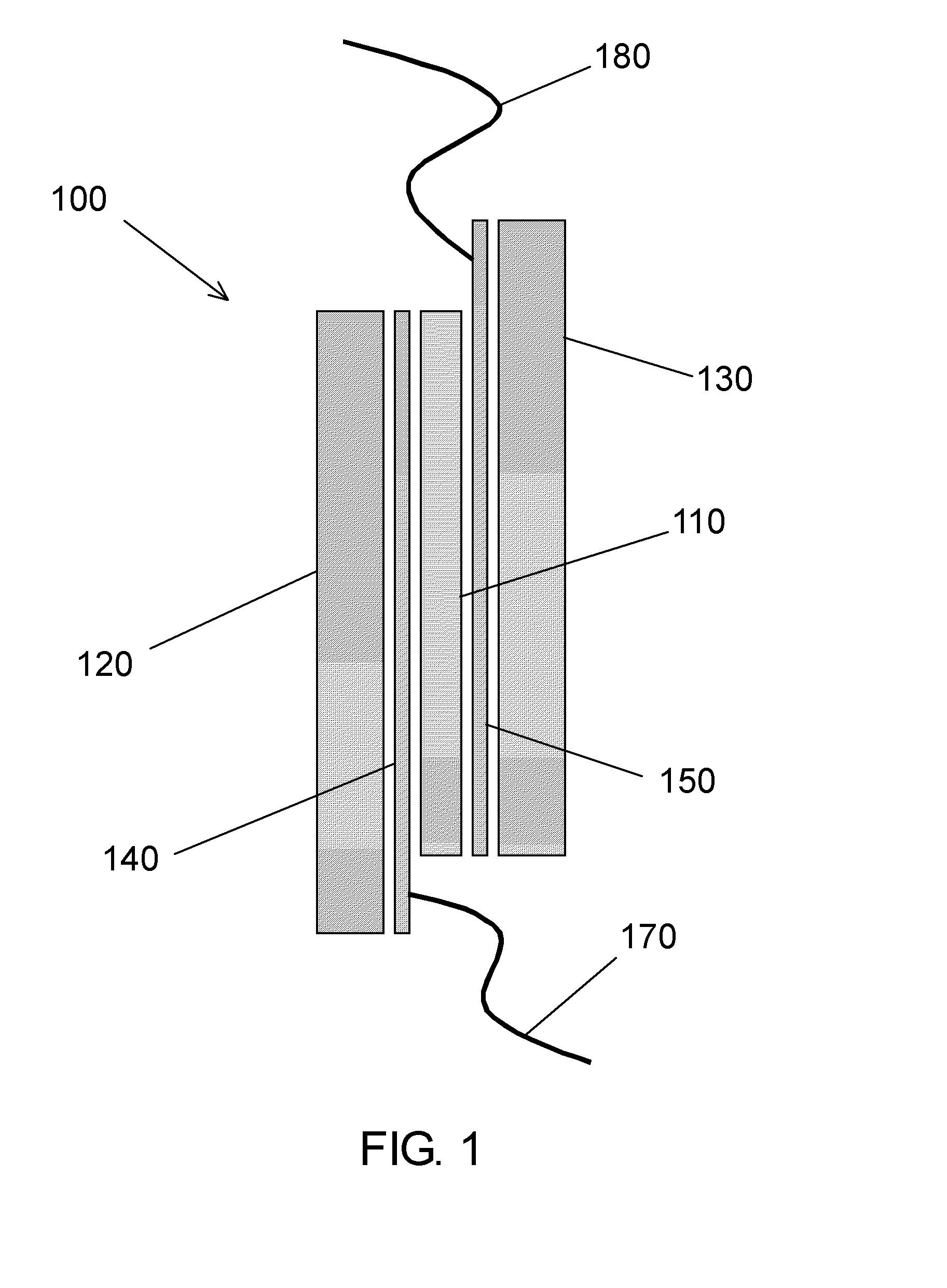
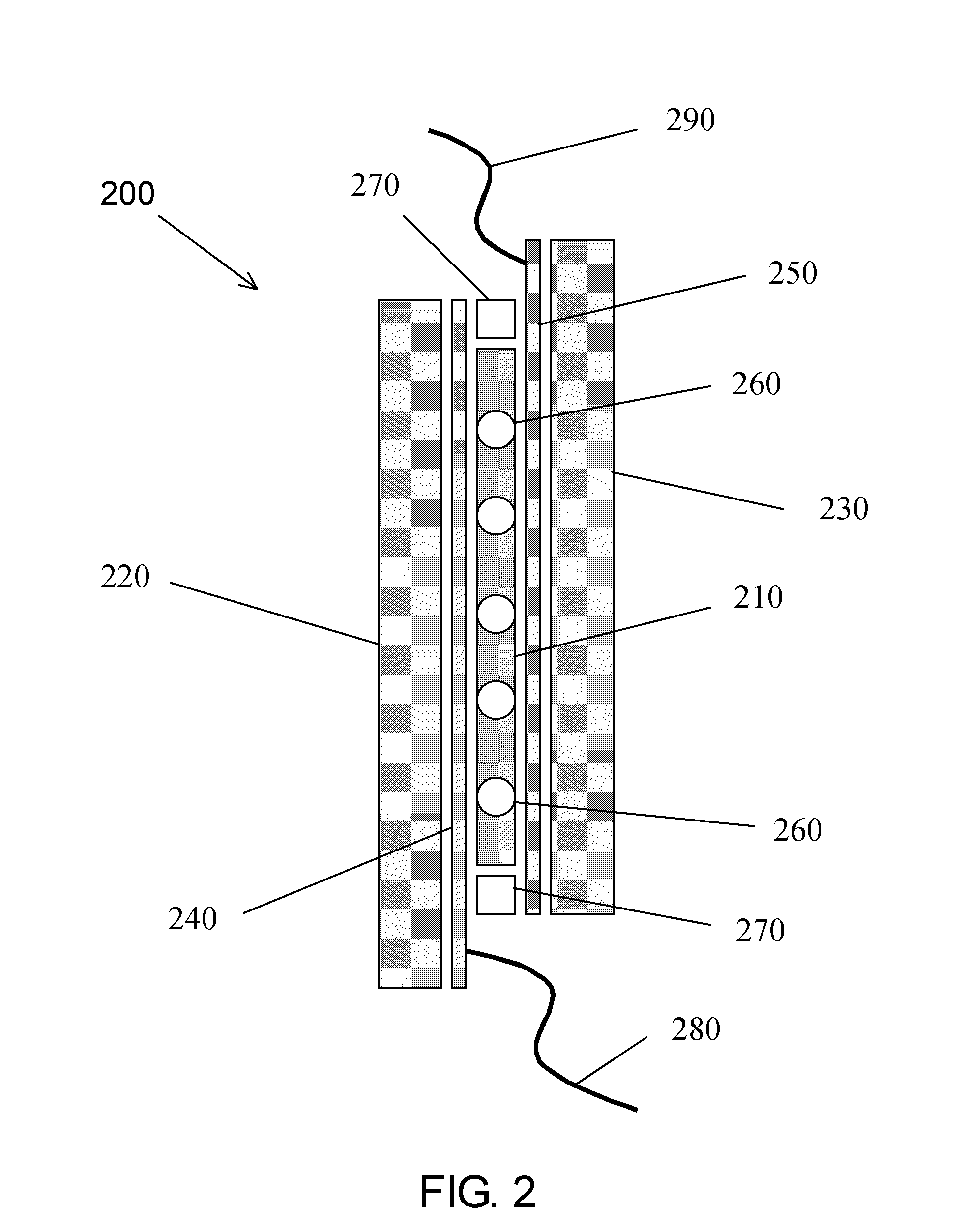
[0034]In accordance with another aspect of the present invention, there is provided a method for preparing a variable transmittance window capable of transitioning from a light state to a dark state on exposure to UV radiation and from a dark state to a light state with application of an electric voltage, comprising the steps of: a) providing the optical filter of the invention; and b) associating said optical filter with at least one substantially transparent surface of said window.

Problems solved by technology

Reversion of photochromics from the dark to light state, however, is slow and cannot be controlled manually.
Photochromics can also be very temperature dependent and tend to break down on exposure to UV light.
As such, photochromics have not proven to be a practical technology for some optical filter applications.
As such, windows made using electrochromic technology can be quite expensive.
This makes liquid crystals only useful for applications such as for privacy glass when being able to see through the optical filter in the dark state is not desirable.
Relatively high voltages required for switching the liquid crystals, expensive manufacturing costs, and temperature dependency have limited the application of liquid crystal technology to indoor applications and electronic devices.
The scattering of light means that SPD devices are typically not optically clear in the dark state.
SPD devices can also be expensive to manufacture and typically require that the particles be suspended in a liquid so they have sufficient mobility to move.
Thermochromic filters darken and lighten in response to temperature changes, typically going darker as it gets hotter and as such cannot be manually controlled.

Method used


Image

  • Variable transmittance optical filter and uses thereof
  • Variable transmittance optical filter and uses thereof
  • Variable transmittance optical filter and uses thereof

Examples


example 1

Preparation of Variable Transmittance Optical Filters

[0274]Method A:

[0275]An ITO coated PET substrate having a thickness of 7 mil (˜178 microns) and a sheet resistance of 50 ohms / square (0050, made by CP Films) is cut into two 15 cm×15 cm sheets. The substrate is prepared by cleaning with a Teknek tacky dust-removing roller and temporarily laminated to glass plates. Steel spacers are placed on the glass around the perimeter of the PET. These spacers act as hard stops, which set the gap for the final pressed device. A switching material, prepared as described below, is placed on the PET to completely fill the gap between the PET sheets when the device is pressed. The switching material is heated to 80-100° Celsius to facilitate dispensing; however, less heat is required for the actual pressing. The second piece of glass-backed PET is placed on top of the other. The PET sheets overlap such that there is some ITO coating exposed, to act as the external electrical contacts. The sandwich...

example 2

Preparation of the Switching Material

[0278]The switching material was formulated to demonstrate how the components of the formulation can be varied. These formulations can be readily adapted to a desired application by a worker skilled in the art, by replacing the listed ingredients with one or more other ingredients in accordance with the present invention.

[0279]2.1 Formulation for Switching Material #1

Ingredient% by WeightPEGDMA 86015% triglyme75% DAROCUR0.01%  lithium perchlorate1%tris(4-bromophenyl)amine (TBPA)6%chromophore:3%TOTAL100% 

[0280]The chromophores that are used in Formulation #1 include:

or a derivative thereof having different functional groups on the four peripheral thiophene rings; or

[0281]The PEGDMA, the triglyme, the lithium percholarate, and the tris(4-bromophenyl)amine are all available for example from Sigma-Aldrich of St. Louis Mo. DAROCUR is a photo-initiator available from CIBA Specialty Chemicals of Basel Switzerland, a division of BASF.

[0282]Formulation #1...

example 3

Optical Properties of Switching Material

[0302]The optical properties of the switching material are tested with samples of the switching material.

[0303]VLT Spectrum

[0304]The VLT spectrum of the switching material that had been prepared according to the formulation described in Example 2.3, was determined for its light and dark state. The procedure uses an Ocean Optics spectrometer to measure the % visible light transmittance of the sample, in its light and dark states, over an electromagnetic spectrum. The samples are prepared according to the method described in Example 2.

[0305]As illustrated in FIG. 5, when the molecules are exposed to UV light, the switching material switches to its dark state resulting in a decrease in the percent transmittance of the material in the visible range between 400 and 750 nm. An electric charge of 2 Volts is then applied to the switching material sample for 3 minutes, causing the sample to revert to its light state. In the light state, more light is p...


PUM

PropertyMeasurementUnit
visible light transmittanceaaaaaaaaaa
sheet resistanceaaaaaaaaaa

Abstract

Variable transmittance optical filters capable of transitioning from a light state to a dark state on exposure to UV radiation and from a dark state to a light state with application of an electric voltage are provided. The optical filters comprise a switching material that comprises one or more chromophores that have electrochromic and photochromic properties.

Description

CROSS REFERENCE TO RELATED APPLICATIONS[0001]This application claims priority from U.S. Provisional Patent Application Ser. No. 61 / 186,055 filed Jun. 11, 2009, U.S. Provisional Patent Application Ser. No. 61 / 186,076 filed Jun. 11, 2009, U.S. Provisional Patent Application Ser. No.[0002]61 / 186,058 filed Jun. 11, 2009, and U.S. Provisional Patent Application Ser. No. 61 / 186,069 filed Jun. 11, 2009. The contents of all of the aforementioned applications are hereby specifically incorporated by reference in their entirety.FIELD OF THE INVENTION[0003]The present invention pertains to the field of variable transmittance optical filters, in particular to an optical filter capable of transitioning from a light state to a dark state on exposure to UV radiation and from a dark state to a light state with application of an electric voltage, devices comprising optical filters of the invention, and uses thereof.BACKGROUND OF THE INVENTION[0004]Optical filters are widely used to control visible an...

Claims


Application Information

Patent Timeline
Patent Type & Authority Applications(United States)
IPC IPC(8): G02F1/153G02B5/23H01R43/00
CPCG02B5/23G02F1/15165G02F2201/086G02F1/1533H01R43/26G02F1/163G02F1/157G02F1/0063G02F1/0018G02C7/102G02C7/101B60J3/04G02B5/223Y10T29/49204Y10T29/49117Y10T156/10E06B9/24G02F1/15G02F1/0126G02F1/153
Inventor LAM, DUHANEBRANDA, NEIL R.
Owner SOLUTIA CANADA INC
Learn More