
Single or multitouch-capable touchscreens or touchpads comprising an array of pressure sensors and the production of such sensors

Inactive Publication Date: 2010-12-16
STEINHAUSER ANDREAS +1
View PDF14 Cites 171 Cited by
  • Summary
  • Abstract
  • Description
  • Claims
  • Application Information

AI Technical Summary

Benefits of technology

[0015]The object of the invention referred to in claim 1 is to manufacture, very efficiently and inexpensively, a single or multitouch-capable display or touchpad that is both sturdy and insensitive to interference and that can also be miniaturised easily and used in mobile devices.

Problems solved by technology

These methods are either difficult or impossible to miniaturise or are very expensive.
So far an inexpensive, sturdy and easily miniaturisable solution is lacking.
At present such imaging methods cannot be produced flat enough to be used in mobile devices.
However, by using the LEDs the energy consumption is comparatively high with the result that the method is hardly suitable for use in mobile devices.
Capacitive sensor technology is susceptible to interference from stray radiation and furthermore cannot penetrate a display which is common at present.
Such interfaces are very expensive as indium is one of the rarest elements on earth.
Furthermore, they are not perfectly transparent with the result that readability of the screen suffers and any reflective effects can act disruptively on the interface.
Inductive methods are based on the highly disruptive aspect that they can only function with special styluses that contain electronic components.
These cannot be used, however, to detect more than one finger or stylus.
In addition, the surface may not be flexible or must by reinforced if necessary against bending otherwise interpolation cannot be performed with sufficient accuracy.

Method used


Image

  • Single or multitouch-capable touchscreens or touchpads comprising an array of pressure sensors and the production of such sensors
  • Single or multitouch-capable touchscreens or touchpads comprising an array of pressure sensors and the production of such sensors
  • Single or multitouch-capable touchscreens or touchpads comprising an array of pressure sensors and the production of such sensors

Examples


Embodiment Construction

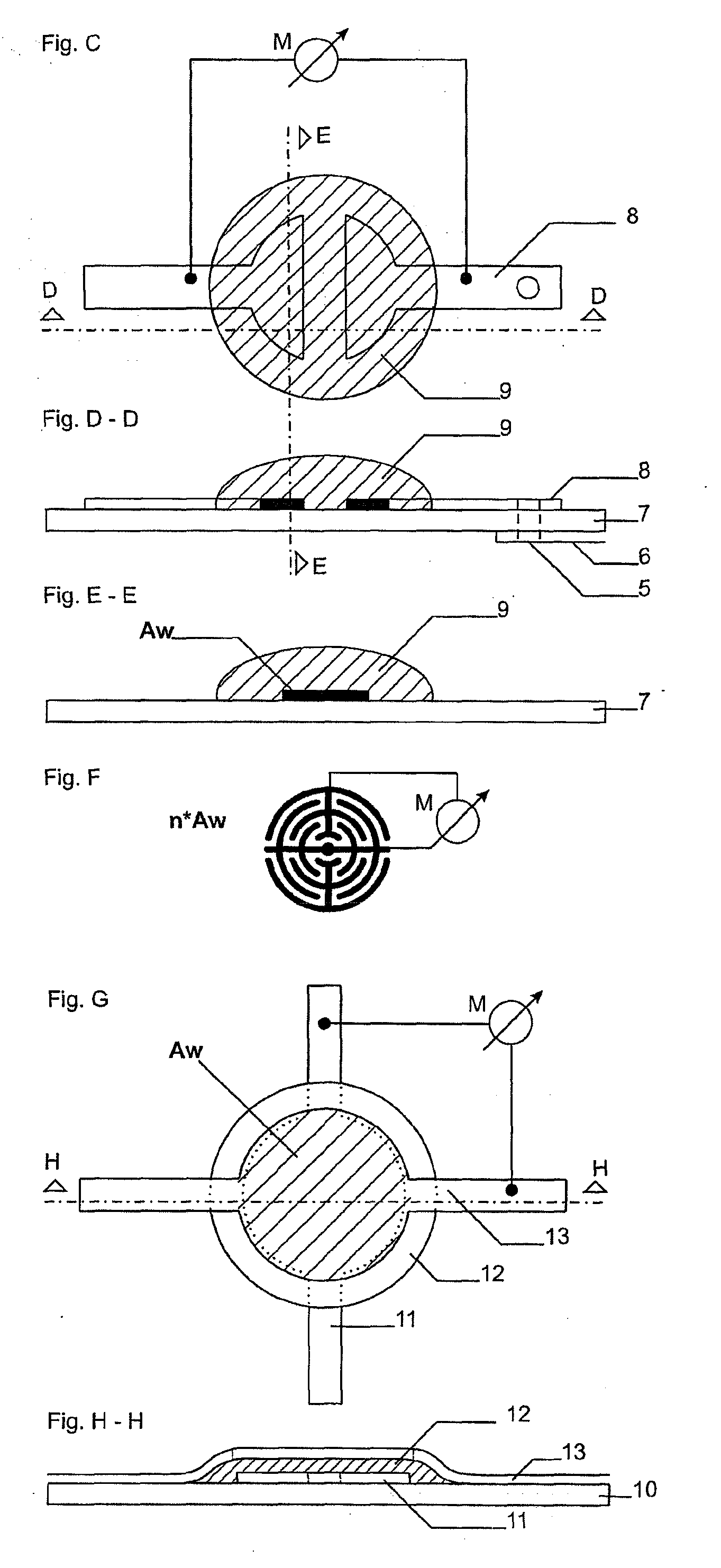
[0027]The Figures referred to above will be explained in detail in the following.

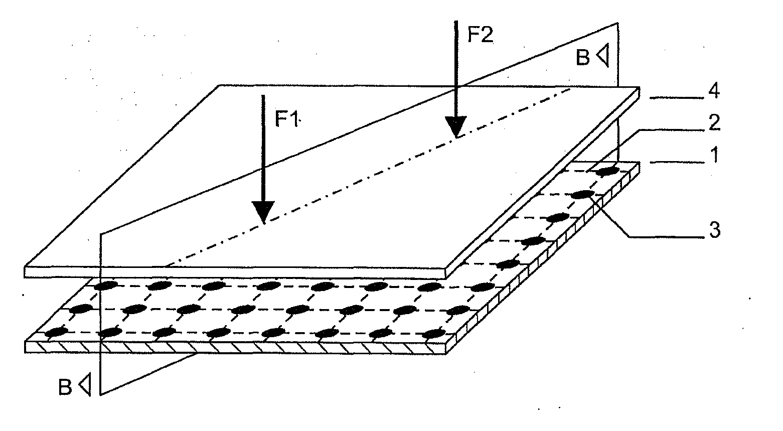
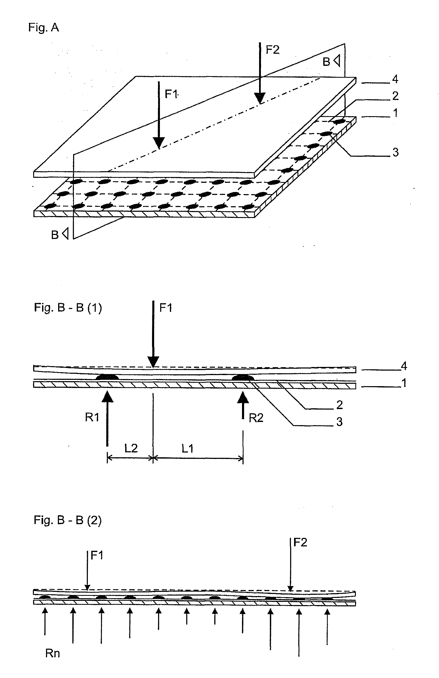
[0028]Fig. A shows a perspective layered construction of the invention having a sensor layer and a display layer.

[0029]If a finger or other object (F1) touches the display or the surface (4), this pressure is transferred variably to the underlying sensor (R1 and R2 in Fig. B-B (1))according to the lever rule. By applying the lever rule, paths L1 and L2 can already be clearly determined for all the sensors and therefore the position of the finger on the surface even when using only three pressure sensors, though it is not possible in this way to differentiate a second contact.

[0030]However, as in addition the display or surface is slightly elastic, the surface is easily and reversibly deformed at the point of contact (Fig. B-B (2)). This deformation leads to the sensors close to the contact being loaded more heavily and those further away more lightly than would be expected according to the lever rule. T...


PUM


Abstract

A multitouch-capable touchscreen is realized in that a large number of pressure sensors are attached under a flexible surface and thus both the pressure distribution and also the deformation of the surface is measured. Local pressure maxima occur due to the flexibility of the surface material with associated deformation on contact. As several local pressure maxima can exist, it is thus also possible to identify a plurality of contacts simultaneously. It is possible from the strength of pressure and pressure distribution to determine the force that is used for pressing such that this information can also be used in the user interface. Such sensors can be produced very efficiently and inexpensively by printing an ink that changes its resistance under pressure onto PCB tracks designed as sensor surfaces. The PCB tracks and the sensor surfaces can also be printed out using an ink with as low a resistance as possible.

Description

[0001]The invention relates to a touchscreen or touchpad that determines the position of the contact.BACKGROUND[0002]Currently there are several methods of interaction with machines or computers, e.g. mouse, keyboard, touchscreen, touchpad and various sensors.[0003]Touchscreen technology in particular is becoming increasingly popular as here direct interaction with the device is possible with immediate feedback via the screen. In addition, with mobile devices in particular, the space-saving is relevant as display and touch interface combined take up less room than display plus, for example, a keyboard. However, even touchpads, that is to say touch-sensitive surfaces, are now the most common replacement for a mouse, e.g. with notebooks.[0004]With the invention of what are referred to as multitouch-capable touch devices (touchscreen or touchpad) with which more than one finger or stylus or other objects can be detected, a completely new interaction becomes possible, e.g. with a plural...

Claims


Application Information

Patent Timeline
IPC IPC(8): G06F3/041
CPCG01L1/205G06F3/045G06F3/044G06F3/0414G06F3/04144
Inventor STEINHAUSER, ANDREASMERIAC, MILOSCH
Owner STEINHAUSER ANDREAS
Learn More