Double-gate field-effect-transistor based biosensor
a biosensor and field effect technology, applied in the field of biosensors, can solve the problems of generating offset errors, requiring maintenance, and difficult miniaturisation, and achieve the effects of reducing manufacturing costs, easy miniaturisation, and reducing manufacturing costs
- Summary
- Abstract
- Description
- Claims
- Application Information
AI Technical Summary
Benefits of technology
Problems solved by technology
Method used
Image
Examples
first embodiment
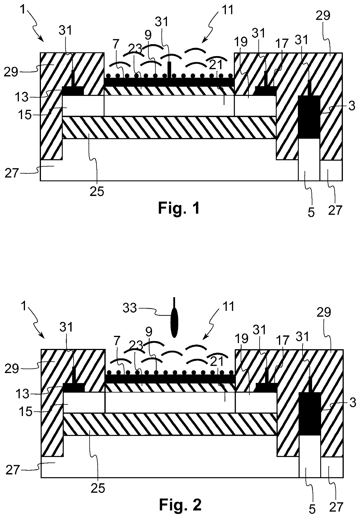
[0018]FIG. 1 is a schematic cross-section view of a multi-gate sensor 1, also referred to as a device, comprising two physically independent or separate gates according to the present invention. In the present description, by a multi-gate device is understood a device comprising at least two gate elements, nodes, terminals or regions. Thus, the device of FIG. 1 could comprise more than two gates. The biosensor 1 of FIG. 1 comprises a field-effect transistor (FET) exposed to a liquid solution. As can be seen in FIG. 1, the transistor comprises a first gate element, referred to as a back gate, comprising a back gate electrode 3 or electrical contact and a back gate doped region 5 in direct contact with the back gate electrode 3. The transistor also comprises a second gate element, referred to as a front gate, in this example comprising a front gate electrode 7 or electrical contact. In the present description, the electrical contacts are metal conductors, but they could instead be any...
third embodiment
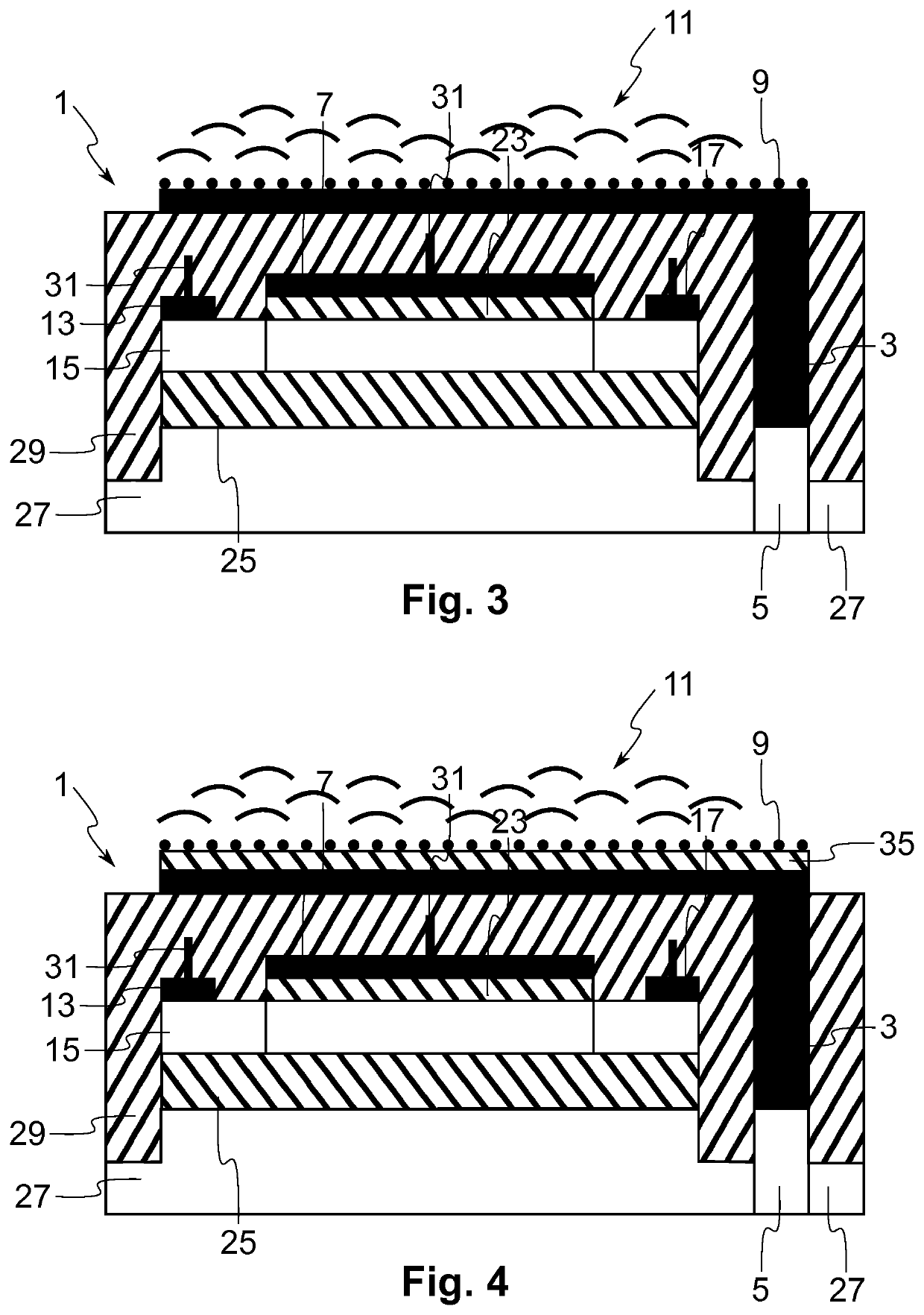
[0034]It is to be noted that the roles of the front and back gates may be inverted. In this case, the operating point of the transistor can be set via the source, drain and front gate biasing. The front gate coupling sets and controls the conductive channel between source and drain doped regions 15, 19 and the back gate stack is in contact with the solution 11. This is the present invention as shown in FIG. 3. It is to be noted that the electrical contact 3 of the back gate is usually not arranged via the back side (bottom) of the SOI substrate (due to the thickness of the base silicon and the parasitics notably) but it is arranged through the front (top) side as is the case also in the configuration of FIG. 3. During the fabrication process, a hole is etched through the BOX layer 25 of the SOI substrate in the location where the back gate contact should be placed and a (metal) plug contact is then formed to provide the electrical contact 3. Such a plug contact to the back gate may ...
PUM
| Property | Measurement | Unit |
|---|---|---|
| thickness | aaaaa | aaaaa |
| thickness | aaaaa | aaaaa |
| thickness | aaaaa | aaaaa |
Abstract
Description
Claims
Application Information
 - R&D
- Intellectual Property
- Life Sciences
- Materials
- Tech Scout
- Unparalleled Data Quality
- Higher Quality Content
- 60% Fewer Hallucinations
Browse by: Latest US Patents, China's latest patents, Technical Efficacy Thesaurus, Application Domain, Technology Topic, Popular Technical Reports.
© 2025 PatSnap. All rights reserved.Legal|Privacy policy|Modern Slavery Act Transparency Statement|Sitemap|About US| Contact US: help@patsnap.com


