
Cooling-control technique for use in a computer system

Active Publication Date: 2010-12-16
ORACLE INT CORP
View PDF6 Cites 38 Cited by
  • Summary
  • Abstract
  • Description
  • Claims
  • Application Information

AI Technical Summary

Benefits of technology

[0022]Another embodiment provides a computer-program product that facilitates the above-described operations of the electronic device and / or the computer system.

Problems solved by technology

However, it is often infeasible to measure the air-flow rate in a computer system.
In particular, sensors that directly measure the air-flow rate often have poor reliability and typically require frequent recalibration (which is economically prohibitive in many applications).
This ‘dual proxy’ relationship typically requires two separate calibration processes, each of which is subject to possible errors.
As the fan ages, wear and other changes will increase friction levels, which make the previously determined PWM-vs.-RPM curve inaccurate.
These inaccuracies can adversely impact the cooling capability and the temperature regulation in a computer system that includes the fan.
However, because of barometric-pressure and altitude variations, the resulting curve may be inaccurate.
As a consequence, these computer systems are usually overcooled at lower altitudes.
While this approach is safe, it wastes energy and results in errors during temperature regulation.
In addition, the RPM-vs.-CFM curve of a computer system may change over time because of air-flow impedance changes, such as flow inhibitors or air-flow ‘short circuits’ in the computer system.
Moreover, air-flow ‘short circuits’ can occur when an operator leaves an access panel in the computer system open.
Consequently, the use of proxy variables to determine the air-flow rate is often subject to errors, which increases the probability of overcooling (which wastes energy, and increases acoustic noise and vibration) or undercooling (which accelerates reliability problems, and can lead to down-time or temperature-induced shutdown of the computer system).
However, the current air-flow rate may be determined without performing air-flow measurements using an air-flow sensor in the computer system.

Method used


Image

  • Cooling-control technique for use in a computer system
  • Cooling-control technique for use in a computer system
  • Cooling-control technique for use in a computer system

Examples


Embodiment Construction

[0031]The following description is presented to enable any person skilled in the art to make and use the disclosure, and is provided in the context of a particular application and its requirements. Various modifications to the disclosed embodiments will be readily apparent to those skilled in the art, and the general principles defined herein may be applied to other embodiments and applications without departing from the spirit and scope of the present disclosure. Thus, the present disclosure is not intended to be limited to the embodiments shown, but is to be accorded the widest scope consistent with the principles and features disclosed herein.

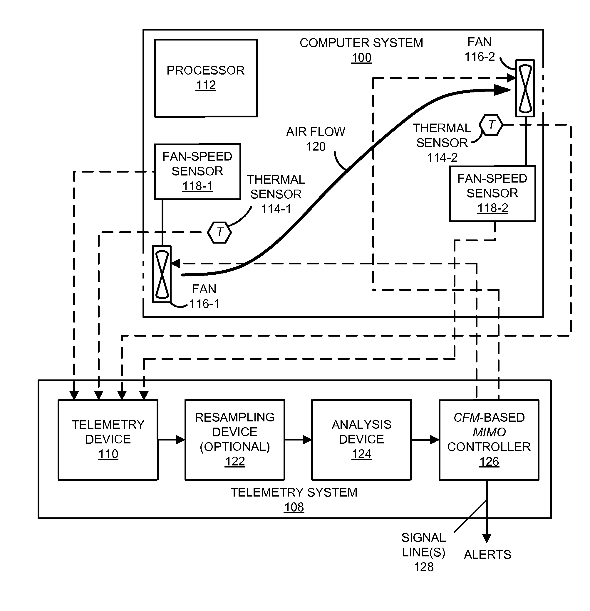
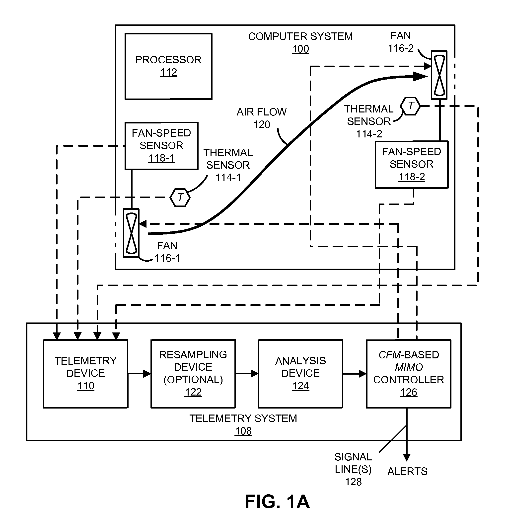
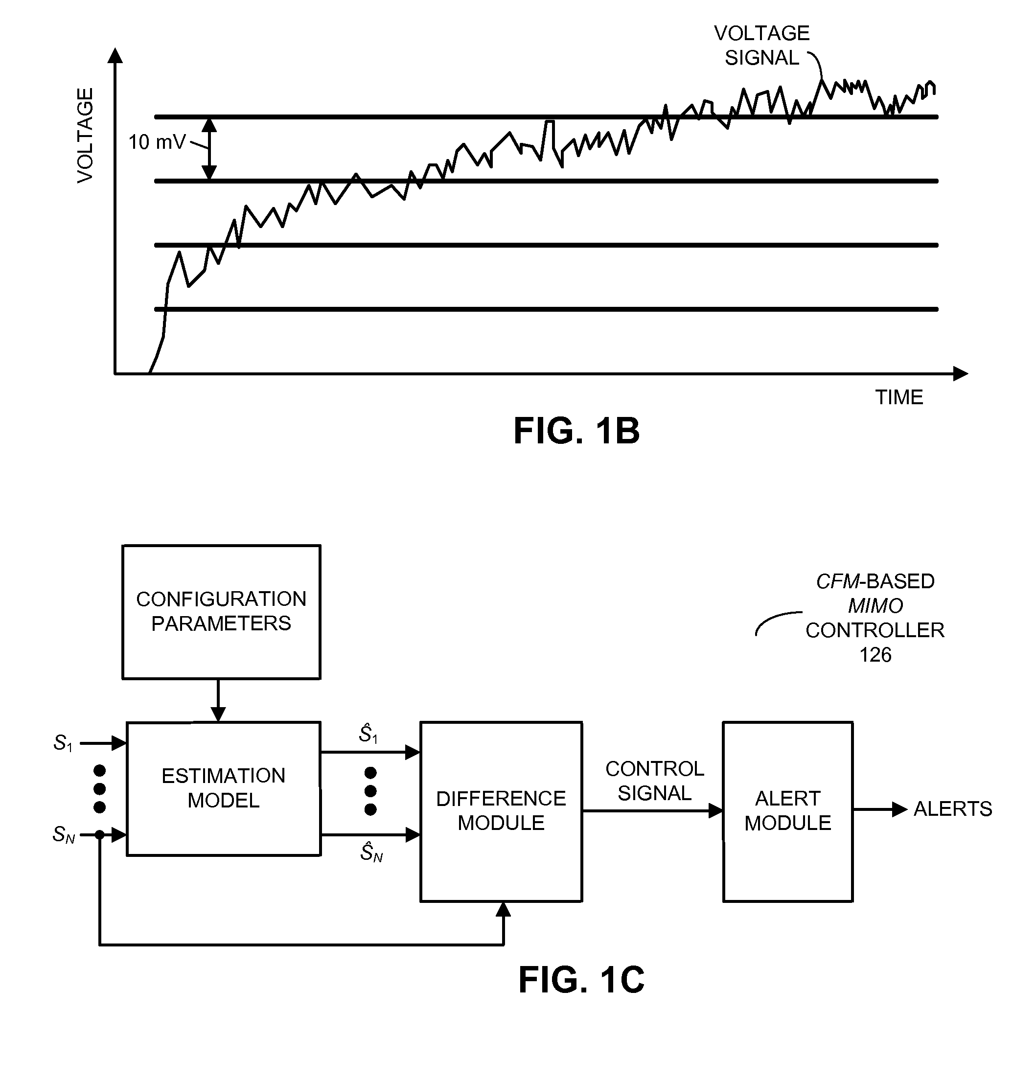
[0032]Embodiments of a computer system, an electronic device in the computer system, a method for providing control signals to a fan in a computer system, and a computer-program product (i.e., software) for use in the computer system are described. During the method, the electronic device receives temperature measurements and a fan-speed mea...


PUM


Abstract

A method for providing control signals to a fan in a computer system is described. During the method, an electronic device receives temperature measurements and a fan-speed measurement performed in the computer system. Using a pattern-recognition model, the electronic device validates the measurements, and excludes any inaccurate measurements, such as those associated with drifting or failed sensors. Next, the electronic device determines control signals for a fan in the computer system using a model of coolant flow in the computer system and / or a slope of a phase-frequency curve of a cross power spectral density function corresponding to a pair of temperature profiles measured, as a function of time, by a pair of thermal sensors. Then, the determined control signals are provided to the fan.

Description

BACKGROUND[0001]1. Field[0002]The present disclosure relates to a techniques for cooling computer systems. More specifically, the present disclosure relates to techniques for generating control signals for a fan in a computer system based on a determined cooling rate of the computer system.[0003]2. Related Art[0004]Convective heat transport mechanisms, such as heat transported by flowing air, are often used to remove the heat generated by components in computer systems. In order to properly regulate the temperature in these computer systems, the rate of heat transport, as indicated by the air-flow rate, and more generally, the mass flow rate (e.g., in cubic feet per minute or CFM) needs to be determined to ensure that it matches or surpasses the rate of heat generation.[0005]However, it is often infeasible to measure the air-flow rate in a computer system. In particular, sensors that directly measure the air-flow rate often have poor reliability and typically require frequent recali...

Claims


Application Information

Patent Timeline
IPC IPC(8): G08B23/00G05D23/19
CPCG05B13/048G06F1/206Y02D10/16G05D23/22G05D23/1931Y02D10/00
Inventor GROSS, KENNY C.VAIDYANATHAN, KALYANARAMAN
Owner ORACLE INT CORP
Learn More