Method for synthesis of titanium dioxide nanotubes using ionic liquids

a titanium dioxide nanotube and ionic liquid technology, applied in the field of titanium dioxide anodization methods, can solve the problems of limited electrical conductivity of electrolyte solutions used in anodization processes of the art, difficulty in anodization process of the art, etc., and achieves improved pv properties, less energy consumption, and high growth rate

Inactive Publication Date: 2010-12-09
UT BATTELLE LLC
View PDF3 Cites 21 Cited by
  • Summary
  • Abstract
  • Description
  • Claims
  • Application Information

AI Technical Summary

Benefits of technology

[0007]In one aspect, the invention is directed to a method for producing titanium dioxide nanotubes wherein titanium metal is anodized while in contact with an electrolytic medium containing an ionic liquid. The method advantageously provides the capability of producing TiO2 nanotubes of finer outer tube diameters (e.g., of or less than 45 nm) and/or higher aspect ratios (e.g., length-to-diameter aspect ratios of at least 100) wherein the resulting nanotubes typically possess one or more improved PV properties. The method

Problems solved by technology

However, several difficulties remain in anodization processes of the art.
For example, the anodization processes of the art are limited in their ability to produce TiO2 nanotubes having improved photovoltaic (PV) properties, particularly those in which an improved PV property results from a finer outer tube diameter (e.g., of or less than 45 nm) and/or higher aspect ratio, e.g., a length-to-diameter aspect ratio of at lea

Method used


Image

  • Method for synthesis of titanium dioxide nanotubes using ionic liquids
  • Method for synthesis of titanium dioxide nanotubes using ionic liquids
  • Method for synthesis of titanium dioxide nanotubes using ionic liquids

Examples


example 1

Preparation of TiO2 Nanotubes

[0098]The ionic liquid 1-butyl-3-methylimidazolium tetrafluoroborate (BMIM-BF4) was mixed with deionized water in a BMIM-BF4: water weight ratio of 0.276: 1, and the resulting fluid used as the electrolyte. The anodization process was conducted on a 0.5 mm thick pure titanium foil (purchased from McMaster-Carr) using a two-electrode DC power supply with a voltage output range of 0-40 V. The titanium foil surface was used as-received (milled) and cleaned with acetone followed by an ethanol rinse before the synthesis. The titanium foil was connected as the working electrode and a piece of platinum mesh was used as the counter electrode. The synthesis was at room temperature, i.e., about 21° C. A constant potential of 10 volts was applied during the synthesis. The time-dependent anodization current was monitored using a multimeter. The current was about 2 mA at the beginning of the synthesis and gradually decreased and stabilized at a level of 0.5 mA for 80...

example 2

Microscopic Analysis of the TiO2 Nanotubes

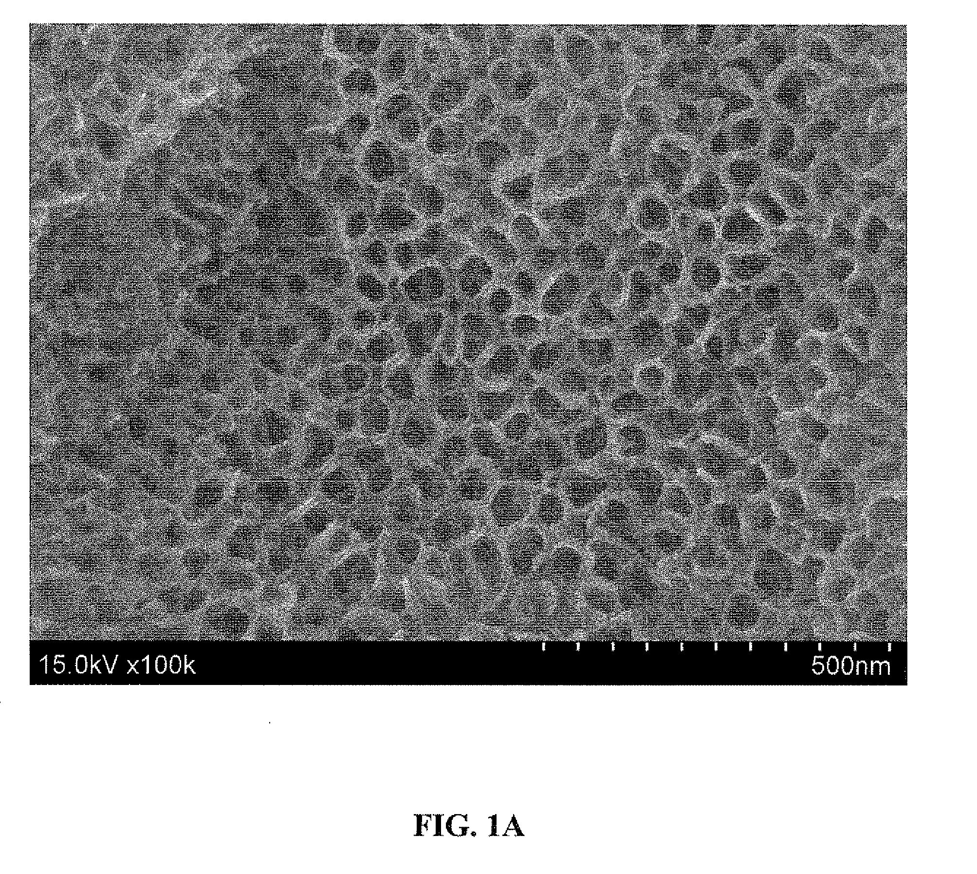
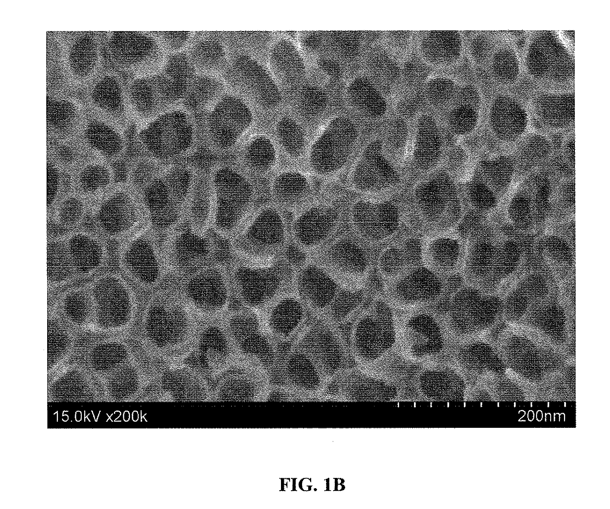
[0099]The as-anodized titanium surface prepared according to Example 1 above was analyzed by scanning electron microscopy (SEM). Before imaging, the surface was ultrasonically cleaned in acetone for 10 minutes during which time the top oxide layer was spalled off to expose the nanotubes underneath.

[0100]FIGS. 1A and 1B show 100,000× and 200,000× magnified, respectively, top view SEM micrographs of the surface. As shown, the SEM images show a thin, dense layer containing a highly ordered array of TiO2 nanotubes covering the as-anodized titanium surface. The nanotubes are shown to have a pore size of 25-35 nm and an outer tube diameter of 40-55 nm.

[0101]FIGS. 2A and 2B show 50,000× and 100,000× magnified, respectively, cross-sectional SEM micrographs of the surface. As shown, the nanotubes have a length of 250-350 nm.


PUM

PropertyMeasurementUnit
Diameteraaaaaaaaaa
Diameteraaaaaaaaaa
Diameteraaaaaaaaaa

Abstract

The invention is directed to a method for producing titanium dioxide nanotubes, the method comprising anodizing titanium metal in contact with an electrolytic medium containing an ionic liquid. The invention is also directed to the resulting titanium dioxide nanotubes, as well as devices incorporating the nanotubes, such as photovoltaic devices, hydrogen generation devices, and hydrogen detection devices.

Description

[0001]This invention was made with government support under Contract Number DE-AC05-00OR22725 between the United States Department of Energy and UT-Battelle, LLC. The U.S. government has certain rights in this invention.FIELD OF THE INVENTION[0002]The present invention relates generally to methods for anodization of titanium, and more particularly, to anodization methods for the preparation of titanium dioxide nanotubes.BACKGROUND OF THE INVENTION[0003]The unique properties of titanium dioxide (TiO2) nanotubes have resulted in their use in several emerging advanced applications, such as their use as water photoelectrolysis catalysts (i.e., for hydrogen generation), photovoltaic components in dye-sensitized solar cells, and as hydrogen gas sensors. There is ongoing interest in using TiO2 nanotubes for numerous other purposes, including as electronic components, microfluidic devices, nanofiltration devices, drug delivery devices, photocatalytic devices, and tissue engineering componen...

Claims


Application Information

Patent Timeline
IPC IPC(8): C40B40/18C25D11/34B32B5/16
CPCC25D3/665Y10T428/2982C25B1/003B82Y30/00B82Y40/00C25D11/26C25B1/55
Inventor QU, JUNLUO, HUIMINDAI, SHENG
Owner UT BATTELLE LLC
Why Eureka
Try Eureka