
Aircraft monitoring and identification system

a technology for identification systems and aircraft, applied in the field of aircraft monitoring, can solve problems such as potential problems, limited information, and small facilities such as general aviation airports, and achieve the effects of aircraft traffic control, and reducing the number of aircra

Inactive Publication Date: 2010-12-09
ALBRIGHT DALE
View PDF2 Cites 53 Cited by
  • Summary
  • Abstract
  • Description
  • Claims
  • Application Information

AI Technical Summary

Benefits of technology

[0009]In one aspect, the invention provides a system for identifying on a continuous basis by tail number aircraft traveling along a pathway at an airport facility wherein sensor means positioned adjacent said pathway detect the presence of an aircraft on the pathway within a detection zone; illuminating means illuminate the aircraft on the pathway within said detection zone in response to the detecting if ambient lighting is below a predetermined level; video recording means record the aircraft including the tail number of the detected aircraft and imbedding an indication of the recording time therein; and the recording is transferred to a remote facility for storage and analysis. Such an analysis may be performed to identify aircraft on watch or alert lists, established locally or globally, report the airport traffic activity for use is assessing fees and obtaining funding, and assisting identification of aircraft excessive noise or other troublesome activities to the population surrounding the facility.
[0015]Another object is to provide an aircraft monitoring system that provides an accurate accounting of identified aircraft departures and arrivals for airport billing and funding purposes.

Problems solved by technology

While such costs can be borne by larger facilities, smaller facilities such as General Aviation Airports have lesser resources and are normally only attended during a portion of the day, usually from sunup to sundown.
One area, however, where limited information is garnered is the arrival and departures of aircraft.
From a security and law enforcement standpoint, this can create potential problems.
The planes could carry passengers and / or cargo posing a danger to airport operations and / or surrounding environs.
Passive surveillance and identification of aircraft has been proposed, but require complex and expensive equipment beyond the means of the smaller facilities.
Even at larger airports, the traffic at the general aviation sector is limitedly monitored.
Notwithstanding the prohibitive costs for implementation, the machine readable code is not presently utilized and would require regulatory mandates for adoption, a lengthy and problematic outcome.
Such a system is intended for commercial fleets and requires onboard equipment not presently available or affordable for general aviation facilities and aircraft.
; and lack of power in remote areas.

Method used


Image

  • Aircraft monitoring and identification system
  • Aircraft monitoring and identification system
  • Aircraft monitoring and identification system

Examples


Embodiment Construction

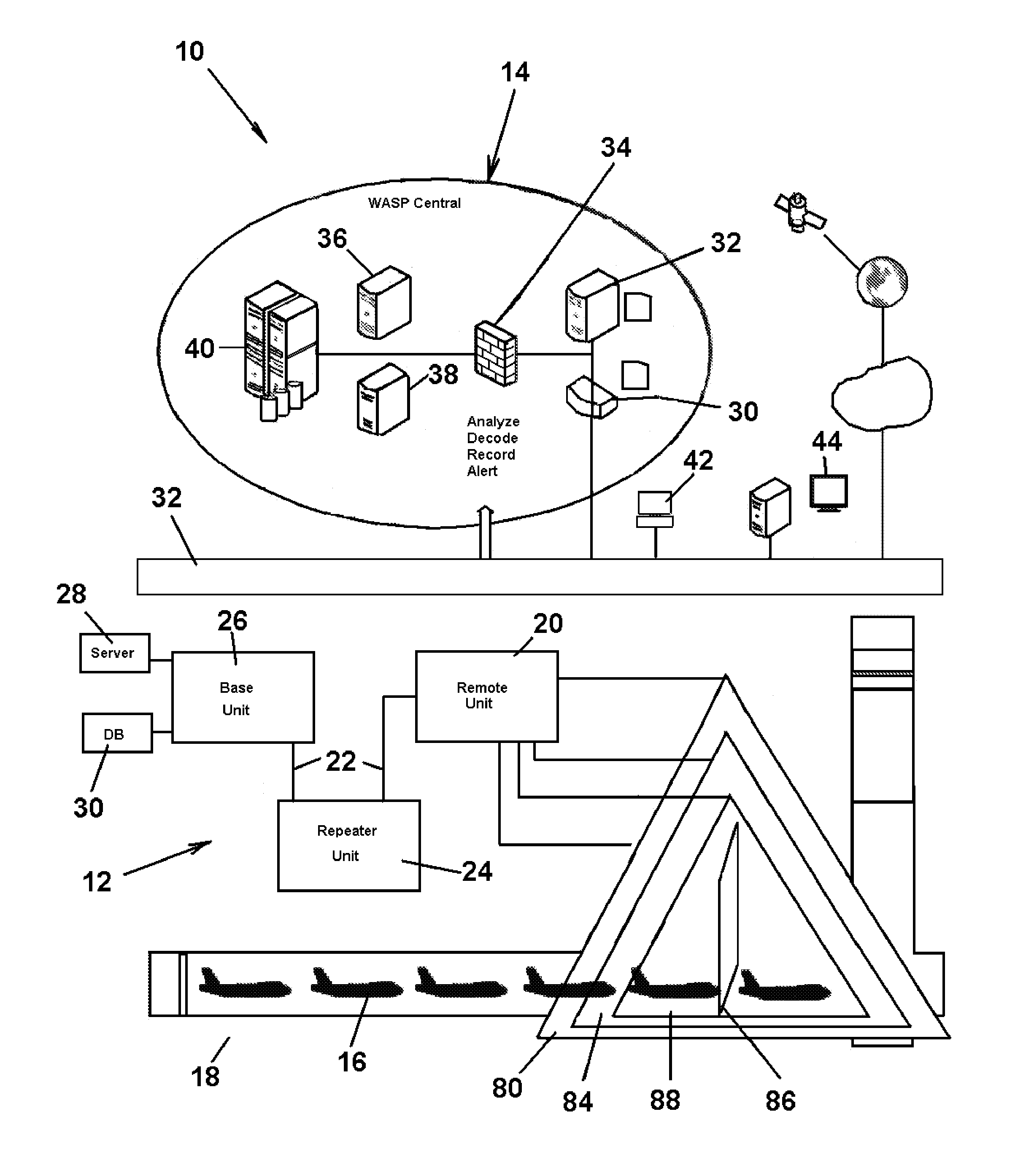
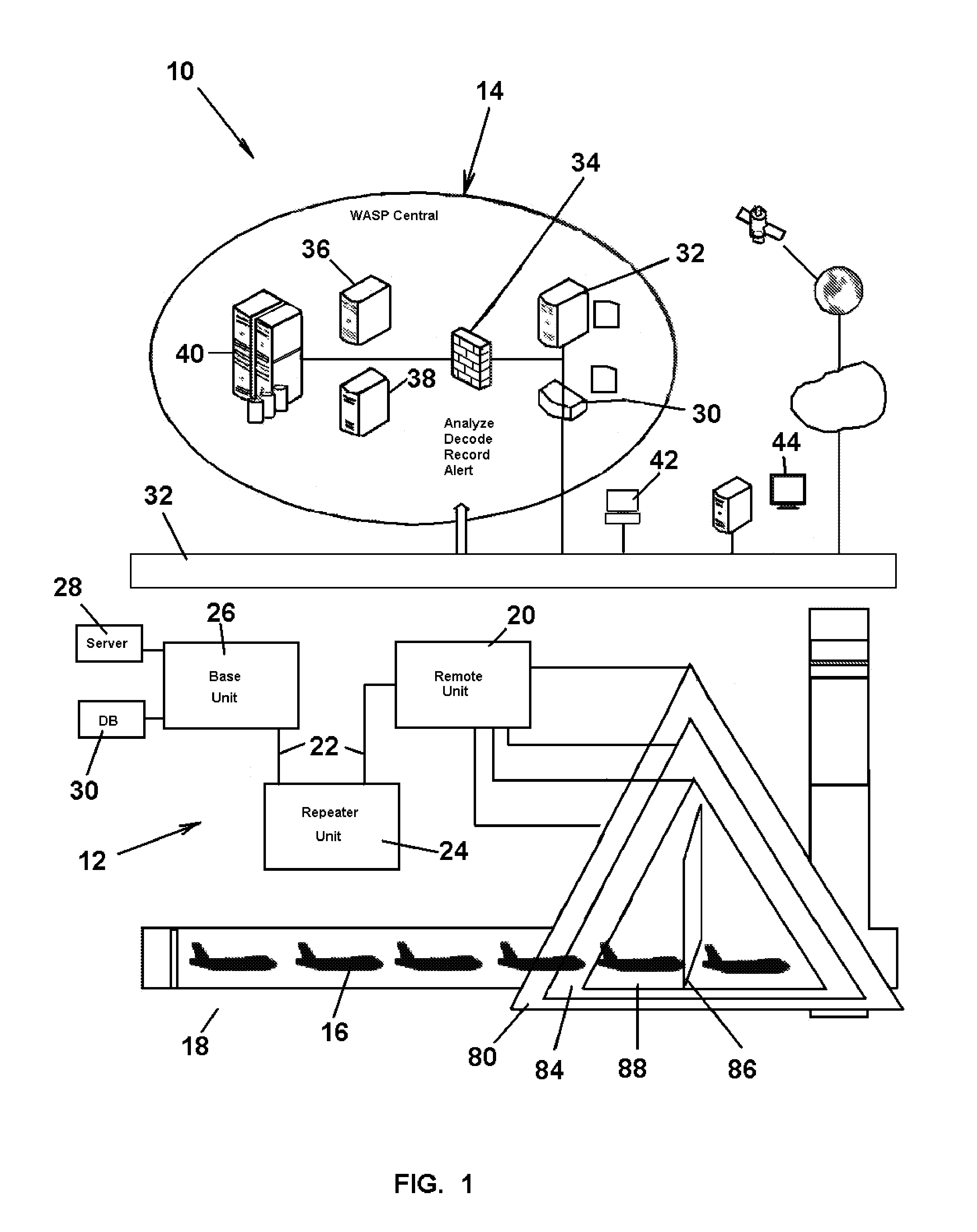
[0024]Referring to FIG. 1, an aircraft monitoring and identification system 10 includes a tail number information system (ATNIS) 12 at an airport that interfaces with a central remote wireless airport surveillance platform (WASP) 14 to detect, identify, capture, decode, and record pictures of all arriving and departing aircraft 16 on airport pathways 18. Based on transferred information thereon, the platform 14 produces electronic alerts of aircraft on watch to authorized parties and reports on detected aircraft activity to interested parties, such as the local airport. The ANTIS system 12 includes free standing remote stations or units 20 positioned at various key locations, such as taxiways and connectors, on the available airport traffic pathways for detecting arrivals and departure movements. A multiplicity of remote stations may be used, dependent on the complexity of the available traffic patterns. The system will be described with reference to a single remote unit for purpose...


PUM


Abstract

An aircraft tail number identification system for detecting, identifying, capturing, decoding, and recording pictures of all arriving and departing aircraft on airport pathways, 24 hours a day, 7 days a week, in all kind of weather.

Description

RELATED APPLICATION[0001]This application claims the benefit of U.S. Provisional Application No. 60 / 912,864 filed on Apr. 19, 2007 in the name of Dale Albright and entitled “Aircraft Tail Number Identification System”.FIELD OF THE INVENTION[0002]The present invention relates to aircraft monitoring and, in particular, to a system for documenting aircraft traffic through the identifying the tail number of aircraft at a facility.BACKGROUND OF THE INVENTION[0003]In the post 9 / 11 world, it was recognized that greater security had to be established at airports serving both national and international planes and passengers. To this end, passenger screening and monitoring throughout the airport complex is common, employing extensive personnel and equipment. Additional scrutiny is directed toward airport personnel and equipment as well as airport perimeters and support facilities. To reduce personnel cost and improve accountability, passive surveillance systems have been proposed for remotely...

Claims


Application Information

Patent Timeline
Patent Type & Authority Applications(United States)
IPC IPC(8): H04N7/18
CPCG08G5/0082
Inventor ALBRIGHT, DALE
Owner ALBRIGHT DALE
Learn More