Method for tracking 3D anatomical and pathological changes in tubular-shaped anatomical structures

a tubular-shaped anatomical and pathological technology, applied in the field of 3d anatomical and pathological changes in tubular-shaped anatomical structures, can solve the problems of different inconsistent definitions of the dsub>max /sub>parameter, take a significant amount of time to extract information, and cannot achieve optimal results

Inactive Publication Date: 2010-12-09
VAL CHUM PARTNERSHIP
View PDF9 Cites 38 Cited by
  • Summary
  • Abstract
  • Description
  • Claims
  • Application Information

AI Technical Summary

Problems solved by technology

Still, currently practiced methods take a significant amount of time to extract information from the medical images, and as a result do not achieve optimal results in a fast and efficient manner.
The prior art teaches various methods for computing the value of Dmax, leading to different inconsistent definitions of the Dmax parameter.
In addition, current measurement methods typically generate intra- and inter-observer variability as well as result in systematic overestimation of the Dmax value as they use either rough estimation based on the appearance of the aneurysm or cumbersome and time-consuming manual outlining of aneurysm anatomy or pathology on sequences of patient images.
Also, as current segmentation techniques use contrast agents that only enable visualization of the aneurysm lumen and not visualization of the thrombus, the latter cannot be segmented using these methods, although it is critical in determining the value of Dmax.
Current segmentation techniques further make it difficult to control the quality of the segmentation as well as correct any mistakes generated by the software.

Method used


Image

  • Method for tracking 3D anatomical and pathological changes in tubular-shaped anatomical structures
  • Method for tracking 3D anatomical and pathological changes in tubular-shaped anatomical structures
  • Method for tracking 3D anatomical and pathological changes in tubular-shaped anatomical structures

Examples


Embodiment Construction

[0034]The present invention is illustrated in further details by the following non-limiting examples.

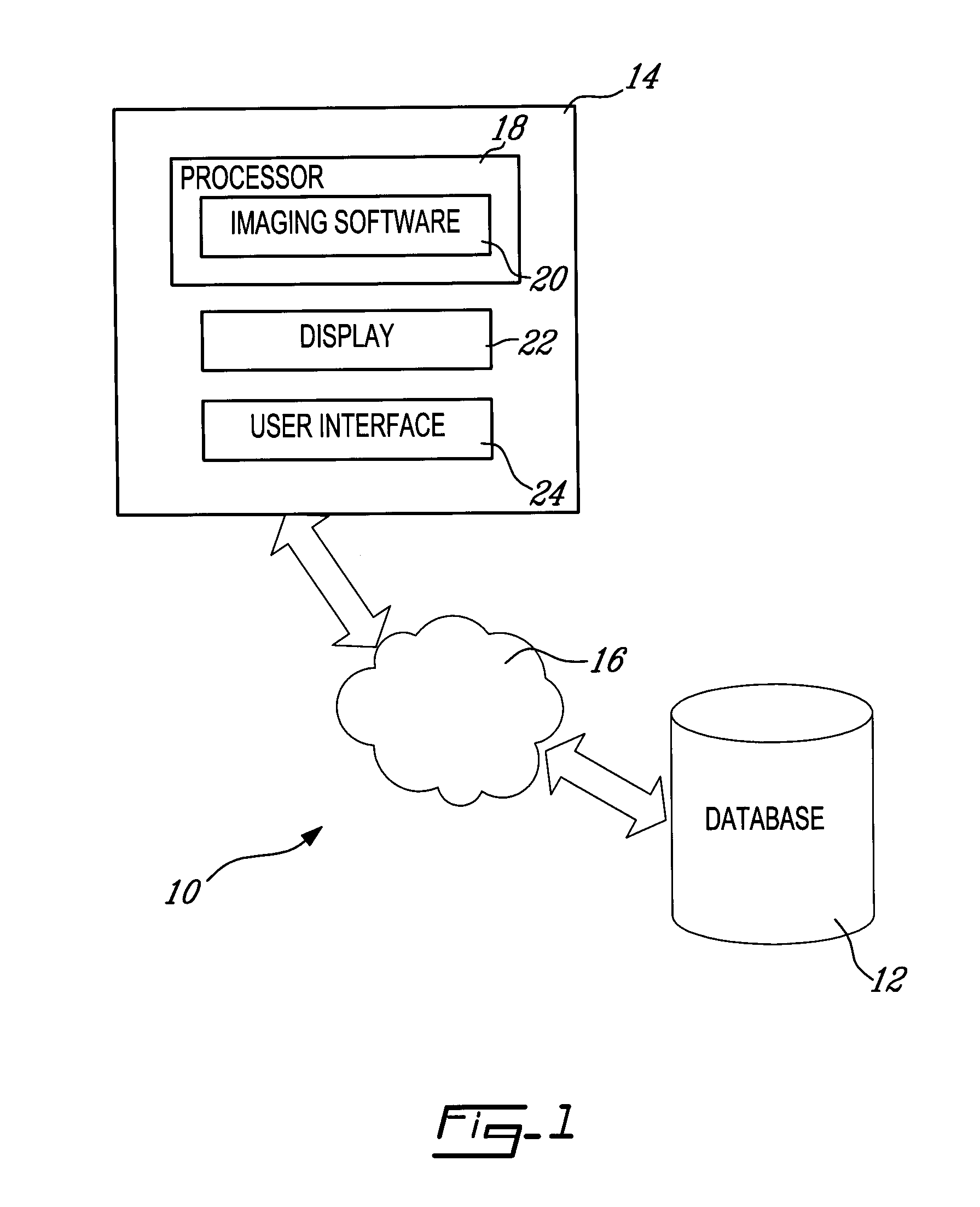
[0035]Referring to FIG. 1, and in accordance with an illustrative embodiment of the present invention, a system for processing and analyzing medical images, generally referred to using the reference numeral 10, will now be described. The system 10 comprises a database 12 for storing patient images and a workstation 14 for accessing the stored images through a communications network 16, such as a Local Area Network (LAN). The workstation 14 comprises a processor 18, on which an imaging software module 20 responsible for processing images retrieved from the database 12 is installed. The workstation 14 further comprises a display 22 and a user interface 24 (e.g. a mouse and keyboard), which enable users to interact with the imaging software 20 by displaying and manipulating image data in response to input commands. The display 22 and the user interface 24 thus enable users to visualize ...


PUM


Abstract

A method for visualizing the anatomy of a region of interest of a tubular-shaped organ based on acquired three-dimensional image slices of the region of interest. Prior to segmentation, reference markers are positioned interactively in the image slices, a minimum curvature path connecting the reference markers is automatically extracted and cross-sectional images are interpolated along a plane normal to a tangent vector of the minimum curvature path. A segmented area corresponding to the region of interest is then delimited in each cross-sectional image and, using this segmented area, a three-dimensional surface representation of the region of interest is computed to readily quantify attributes, such as a maximal diameter and a volume, of the region of interest. When the image sets are acquired in different imaging geometries, the image sets may further be co-registered prior to segmentation, resulting in image sets superimposed in the same geometrical reference frame.

Description

CROSS REFERENCE TO RELATED APPLICATIONS[0001]This application claims priority on U.S. Provisional Application No. 60 / 938,078, filed on May 15, 2007 and which is herein incorporated by reference in its entirety.FIELD OF THE INVENTION[0002]The present invention relates to a method for tracking 3D anatomical and pathological changes in tubular-shaped anatomical structures.BACKGROUND OF THE INVENTION[0003]Medical imaging is increasingly used to study the changes in size and shape of anatomical structures over time. As these changes often serve as indicators of the presence of a disease, extraction of quantitative information from such medical images has many applications in clinical diagnosis.[0004]Conventional practice is to outline anatomical structures by image segmentation, a fundamental step of image analysis, during which anatomical and pathological structure information is typically extracted from patient image data. Image segmentation allows various relevant anatomical structure...

Claims


Application Information

Patent Timeline
Patent Type & Authority Applications(United States)
IPC IPC(8): G06K9/00G06T15/00
CPCA61B5/055A61B6/481A61B6/504G06T7/0081G06T7/0089A61B6/5247G06T2207/10081G06T2207/20092G06T2207/20116G06T2207/30101G06T2200/08G06T7/11G06T7/149
Inventor KAUFFMANN, CLAUDE
Owner VAL CHUM PARTNERSHIP
Why Eureka
Try Eureka