
High-frequency line structure on resin substrate and method of manufacturing the same

a technology of high-frequency line structure and resin substrate, which is applied in the direction of waveguides, electrical equipment, antennas, etc., can solve the problems of further increasing so as to reduce the propagation loss of high-frequency signals

Active Publication Date: 2010-12-09
SHINKO ELECTRIC IND CO LTD
View PDF7 Cites 12 Cited by
  • Summary
  • Abstract
  • Description
  • Claims
  • Application Information

AI Technical Summary

Benefits of technology

[0009]In one aspect of the invention, the present disclosure provides a high-frequency line structure on a resin substrate and a method of manufacturing the same which are adapted to reduce the propagation loss of a high frequency signal.

Problems solved by technology

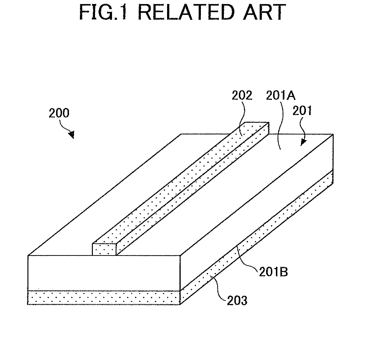
The high-frequency line structure 200 according to the related art has a problem that the propagation loss of the high frequency signal will be increased if the length of the signal wiring 202 is increased.
Electromagnetic waves or magnetic fields which are the components of the high frequency signal are leaked out from the signal wiring 202 into the air, and the high-frequency line structure 200 according to the related art has a problem that the propagation loss of the high frequency signal will be further increased.

Method used


Image

  • High-frequency line structure on resin substrate and method of manufacturing the same
  • High-frequency line structure on resin substrate and method of manufacturing the same
  • High-frequency line structure on resin substrate and method of manufacturing the same

Examples


Embodiment Construction

[0032]A description will now be given of embodiments of the invention with reference to the accompanying drawings.

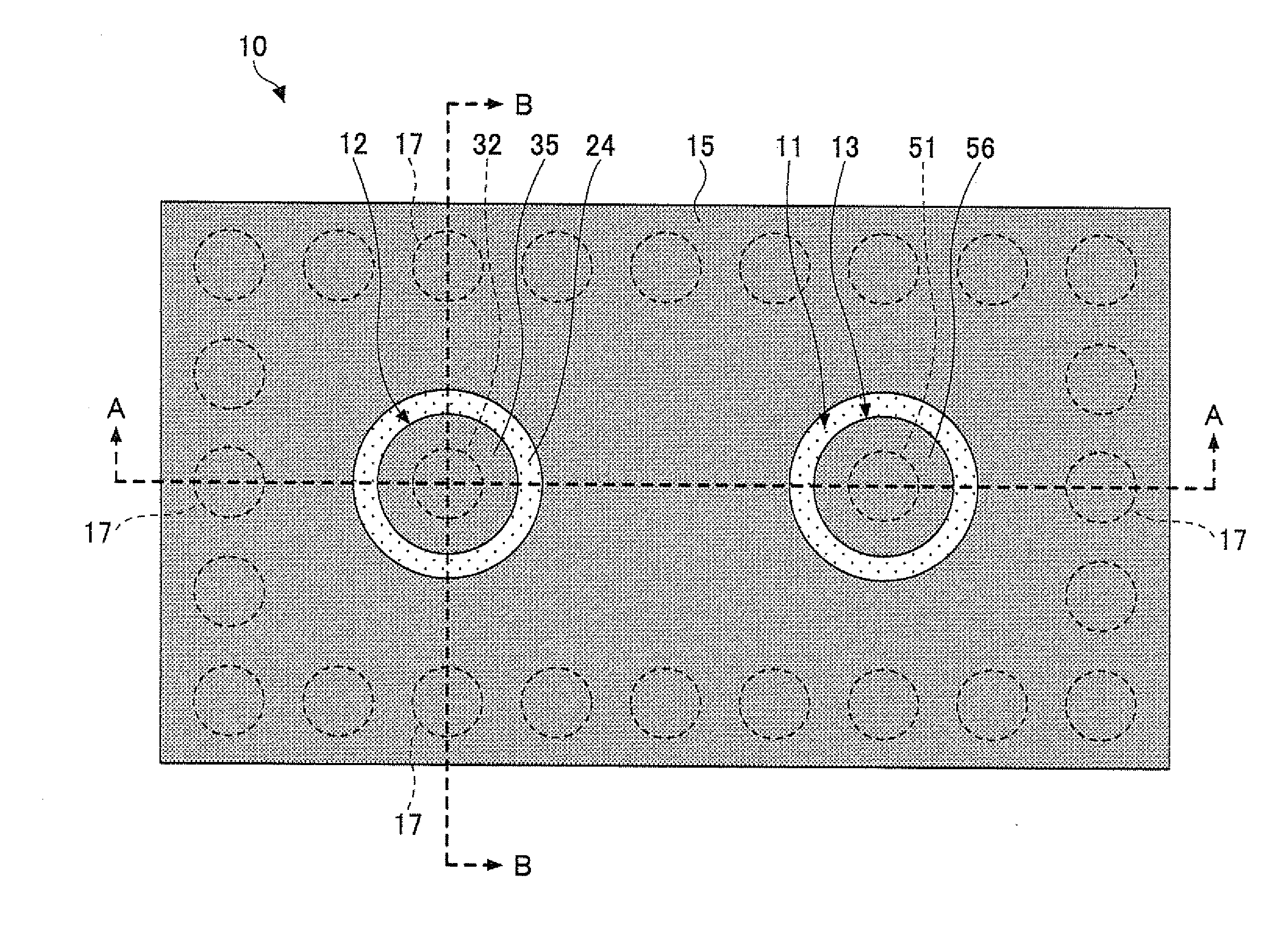
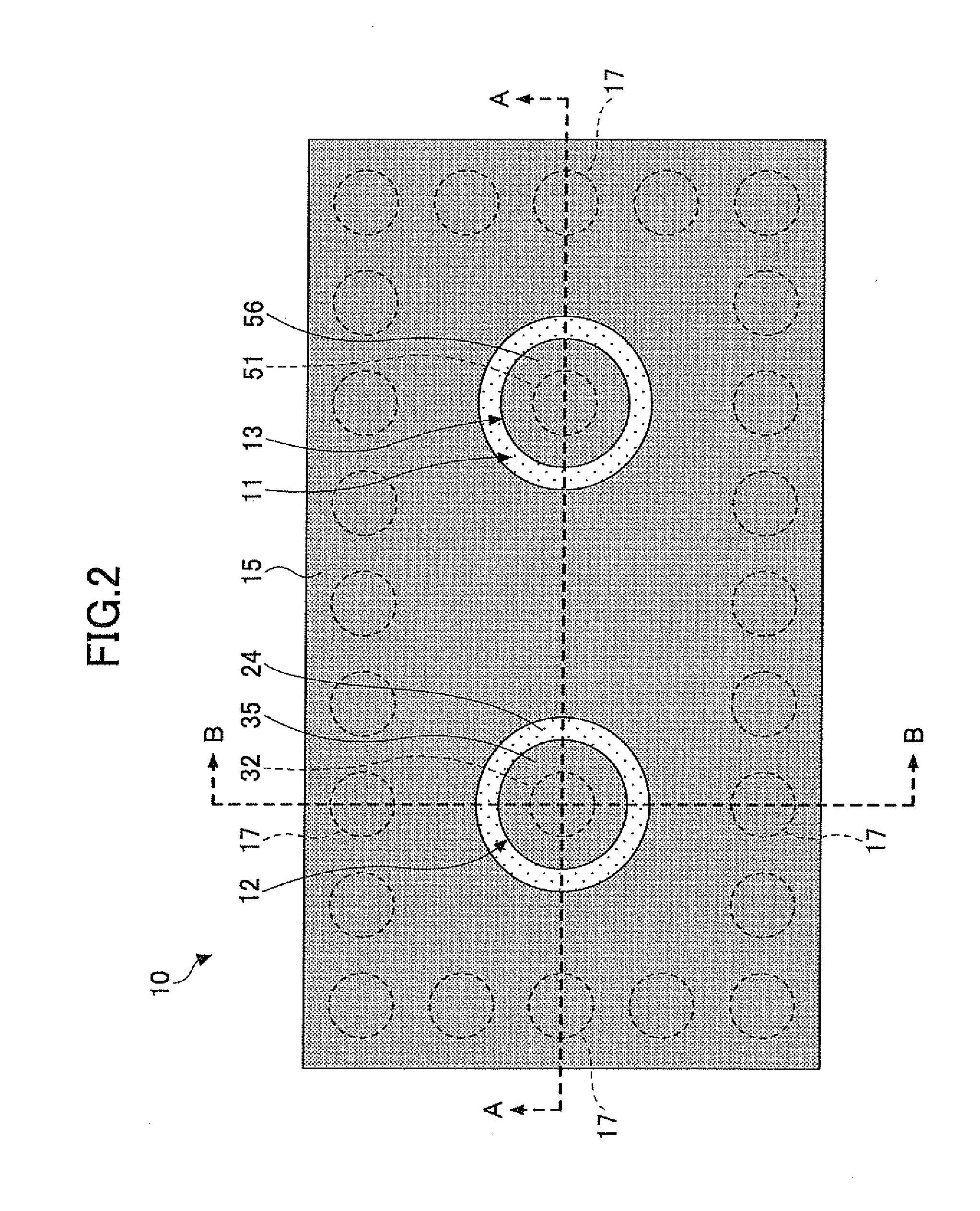
[0033]FIG. 2 is a plan view of a high-frequency line structure on a resin substrate of an embodiment of the invention. FIG. 3 is a cross-sectional view of the high-frequency line structure of this embodiment taken along the A-A line indicated in FIG. 2. FIG. 4 is a cross-sectional view of the high-frequency line structure of this embodiment taken along the B-B line indicated in FIG. 2.

[0034]As illustrated in FIGS. 2 to 4, the high-frequency line structure 10 of this embodiment includes a multi-layered resin substrate 11, a high-frequency-signal input part 12, a high-frequency-signal output part 13, a first metal layer 15, a second metal layer 16, a plurality of penetration holes 17 (each of which is a third penetration hole), a plurality of penetration vias 18, and metal layers 21 and 22.

[0035]In the high-frequency line structure 10 having the composition described above...


PUM

PropertyMeasurementUnit
wavelengthsaaaaaaaaaa
thicknessaaaaaaaaaa
thicknessaaaaaaaaaa

Abstract

A high-frequency line structure includes a multi-layered resin substrate in which insulating layers of a resin are laminated. A high-frequency-signal input part is arranged on the resin substrate to input a high-frequency signal and supply the high-frequency signal to the resin substrate. A high-frequency-signal output part is arranged in the resin substrate to receive the high-frequency signal from the input part and output the received high-frequency signal. A first metal layer is arranged to encircle the input and output pads and electrically insulated from the input and output parts. A second metal layer is arranged on the resin substrate. A plurality of penetration vias are arranged in the resin substrate to encircle the input part and the output part, and each penetration via being connected to the first and second metal layers.

Description

CROSS-REFERENCE TO RELATED APPLICATION[0001]This application is based upon and claims the benefit of priority of Japanese patent application No. 2009-136088 filed on Jun. 5, 2009, the entire contents of which are incorporated herein by reference in their entirety.BACKGROUND OF THE INVENTION[0002]1. Field of the Invention[0003]This invention relates to a high-frequency line structure on a resin substrate and a method of manufacturing the same, the high-frequency line structure being adapted for reducing the propagation loss of a high frequency signal.[0004]2. Description of the Related Art[0005]In wiring substrates for use in mobile communications devices which use radio signals, such as microwaves or millimeter waves, whose radio wavelengths range from approximately one meter down to approximately one millimeter, a high-frequency line structure for propagating a radio signal is provided (for example, see FIG. 1). In the following, a radio signal that is propagated on a high-frequenc...

Claims


Application Information

Patent Timeline
Patent Type & Authority Applications(United States)
IPC IPC(8): H01P3/00H01P11/00
CPCH01P11/001H01P11/003H01P11/002H01P3/121Y10T29/49016
Inventor FUJII, TOMOHARUCHINO, YUKARI
Owner SHINKO ELECTRIC IND CO LTD
Learn More