
Method and apparatus for controlling heating and cooling of transfer unit in precision hot press apparatus

a technology of transfer unit and heat transfer device, which is applied in lighting and heating apparatus, electric/magnetic/electromagnetic heating, instruments, etc., can solve the problems of time lag between the temperature measurement after heat transfer and the control of output, the effect of less heat output and quick temperature control

Inactive Publication Date: 2010-12-09
HITACHI IND EQUIP SYST CO LTD
View PDF6 Cites 4 Cited by
  • Summary
  • Abstract
  • Description
  • Claims
  • Application Information

AI Technical Summary

Benefits of technology

[0014]It is an object of the present invention to provide a method and apparatus for controlling the heating and cooling of a transfer unit in a precision hot press device that reduces the time required by a heating and cooling mechanism to thereby improve productivity thereof.
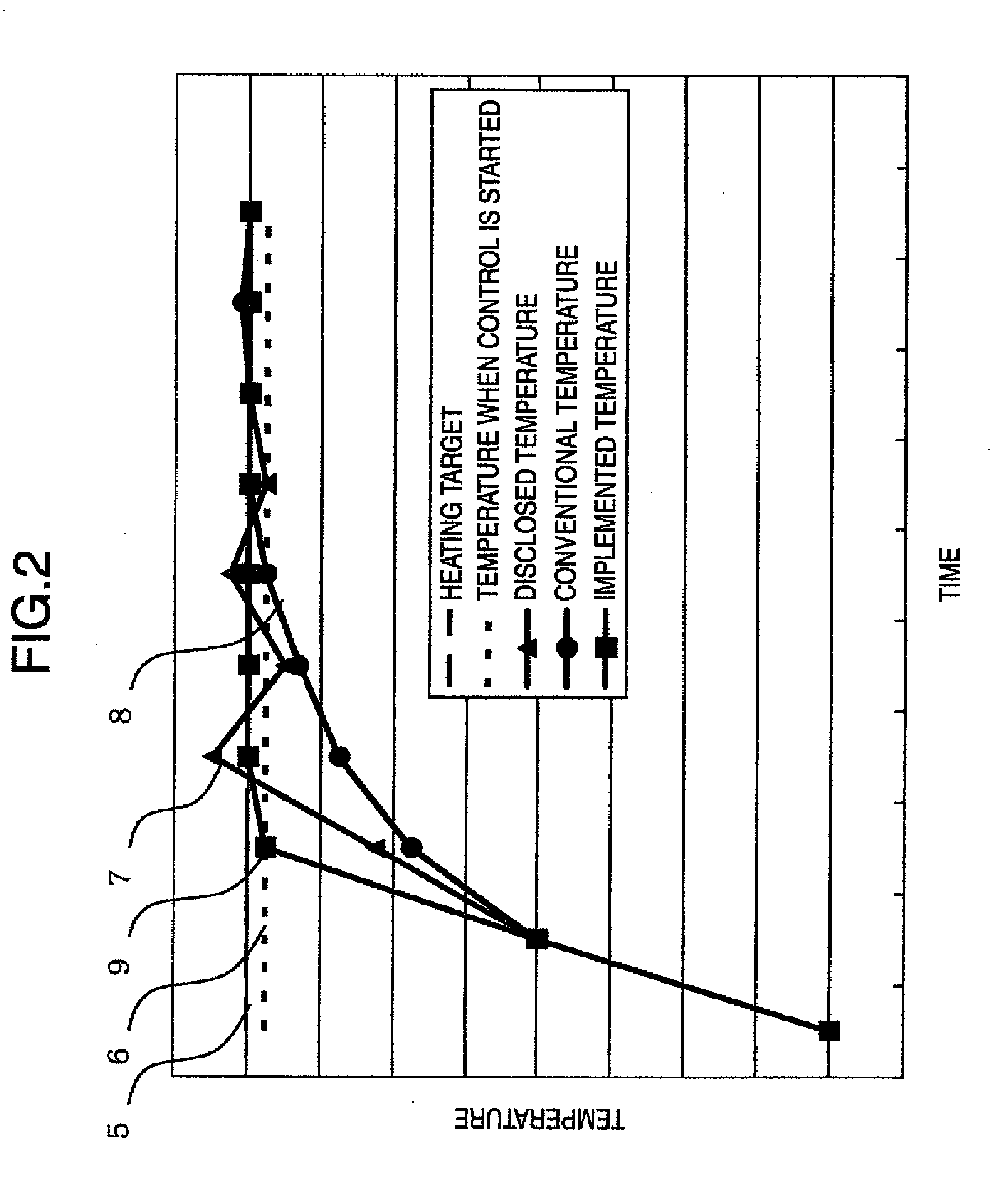
[0017]According to the control of the heating and cooling of the transfer unit in the precision press device of the present invention, the amount of energy (amount of heat) given to or taken from by the heating means or by the cooling means is compared with the energy amount observed to enter into or exit from the transfer unit before the temperature of the transfer unit reaches the target temperature, the amount of surplus or supercooled energy is calculated, and then the transfer unit is heated or cooled based on the amount of surplus or supercooled energy. Therefore, the temperature of the transfer unit is controlled based on the heating or cooling actually provided, thus making it possible to quickly perform control such that the temperature of the transfer unit reaches the target temperature.
[0018]The method and apparatus for controlling the heating and cooling of the transfer unit in the precision press device according to the present invention is capable of quickly performing control such that the temperature of the transfer unit reaches the target temperature by heating and cooling the transfer unit based on the amount of surplus or supercooled energy on the transfer unit. As a result, in a precision hot press device such as a thermal nano imprint device, it is possible to reduce a time period required for heating and cooling processes of the transfer unit, which are repeated for each microstructure transfer, thus making it possible to increase the productivity of the microstructure transfer.

Problems solved by technology

However, since these schemes perform the temperature control from a change in temperatures, there arises a time lag between the temperature measured after heat is transferred and controlling of output.
As a result, the heat output is more suppressed as the current temperature gets closer to the target temperature, thus making it difficult to perform quick temperature control.
In reducing the time required to heat and cool the transfer unit in the precision hot press device, as much as possible, there are some problems to be solved concerning the management of entrance and exit of heat conducted by the heating and cooling mechanism.

Method used


Image

  • Method and apparatus for controlling heating and cooling of transfer unit in precision hot press apparatus
  • Method and apparatus for controlling heating and cooling of transfer unit in precision hot press apparatus
  • Method and apparatus for controlling heating and cooling of transfer unit in precision hot press apparatus

Examples


embodiments

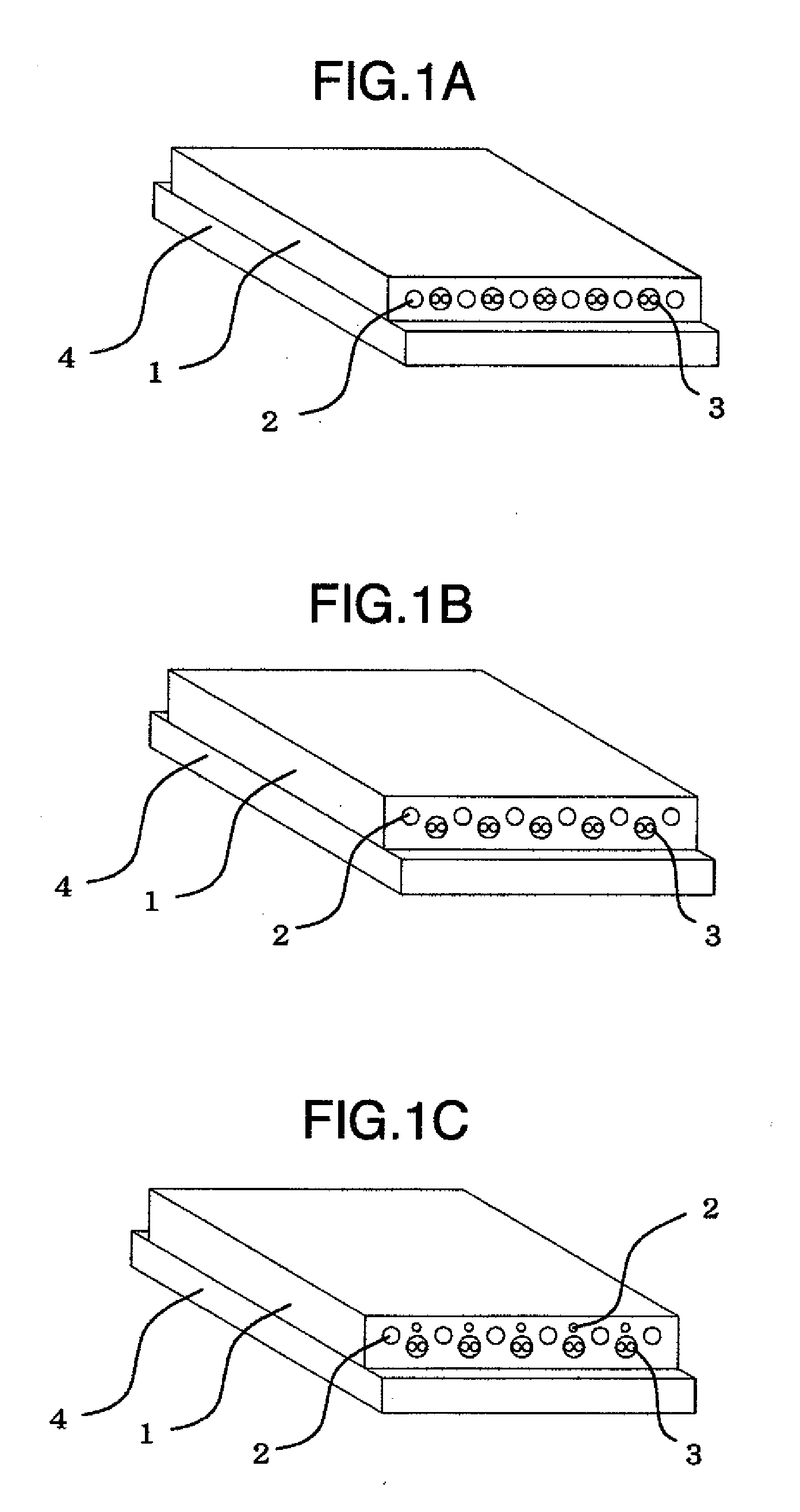
[0026]Embodiments of the method and apparatus for controlling the heating and cooling of the transfer unit in the precision hot press device according to the present invention will be explained with reference to

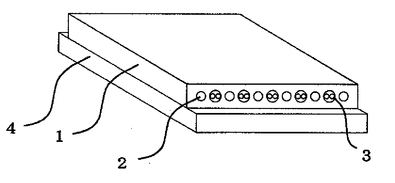
[0027]FIGS. 1A-1C. FIGS. 1A-1C are schematic perspective diagrams illustrating examples, in which the heating and cooling of the transfer unit in the precision hot press device is controlled, according to the present invention. Since the structure of the principal parts including the transfer unit of the precision hot press device is the same as that illustrated, for example, in FIG. 5, another explanation thereof is omitted here. The transfer unit comprises a heating and cooling mechanism 1 and a heat insulation unit 4, and is structured not to externally dissipate thermal energy generated in the heating and cooling mechanism 1. The heating and cooling mechanism 1 is formed with cooling paths 2 for flowing a heating medium 3 and a cooling medium.

[0028]In the heating and cool...


PUM

PropertyMeasurementUnit
temperatureaaaaaaaaaa
microstructureaaaaaaaaaa

Abstract

A method and apparatus for controlling heating and cooling of a transfer unit in a precision hot press device capable of suppressing overheating and supercooling, and of performing quick heating and cooling, wherein the method and apparatus compares an amount of energy (amount of heat) given to the transfer unit or taken from the transfer unit by a heating unit or a cooling unit with an amount of energy observed to enter into or exit from the transfer unit before the temperature of the transfer unit reaches a target temperature, calculates an amount of surplus or supercooled energy from a difference between the two energy mounts, and heats or cools the transfer unit based on the amount of surplus or supercooled energy.

Description

INCORPORATION BY REFERENCE[0001]The present application claims priority from Japanese application JP 2009-135874 filed on Jun. 5, 2009, the content of which is hereby incorporated by reference into this application.BACKGROUND OF THE INVENTION[0002]The present invention relates to a method and apparatus for controlling heating and cooling of a transfer unit, which is applied to a precision hot press device capable of highly flat and microstructure transfer, and is particularly applied to a microstructure transfer mold and a microstructure transfer device. The microstructure transfer mold and microstructure transfer device press an original plate (microstructure transfer mold), which is formed with a fine rugged pattern on the surface thereof and serves as a transfer source, against a substrate (transferred body) to which the pattern is transferred, thus transferring and forming the fine rugged pattern on the surface of the substrate. More particularly, the present invention relates t...

Claims


Application Information

Patent Timeline
Patent Type & Authority Applications(United States)
IPC IPC(8): F25B29/00H05B6/02
CPCB29C35/02B29C35/0288B29C35/0805B29C59/02B29C2035/0811B29C2035/0822G03F7/0002B29C2035/1633B29C2035/1658B30B15/064B82Y10/00B82Y40/00B29C2035/1616
Inventor SHIMAO, DAISUKEKURATA, TAKASHI
Owner HITACHI IND EQUIP SYST CO LTD
Learn More