Eureka AIR delivers breakthrough ideas for toughest innovation challenges, trusted by R&D personnel around the world.

Reactors for forming foam materials from high internal phase emulsions, methods of forming foam materials and conductive nanostructures therein

a technology of high internal phase and foam material, which is applied in the direction of moving filter element filter, separation process, filtering, etc., can solve the problems of low polymer thermal conductivity, impede the conversion and crosslinking of polymers, and short carbon nanotubes produced by conventional methods

Active Publication Date: 2010-12-09
VORSANA INC
View PDF17 Cites 19 Cited by
  • Summary
  • Abstract
  • Description
  • Claims
  • Application Information

AI Technical Summary

Benefits of technology

[0010]According to some embodiments, a method for forming a polymeric foam can include: axially feeding a high internal phase emulsion (HIPE) including an aqueous phase and an oil phase into a workspace defined between opposed counter-rotating centrifugal impellers having a com

Problems solved by technology

Low polymer thermal conductivity frustrates heating the interior of the foam from the outside.
An unsolved problem in the art of HIPE manufacture is the auto-acceleration effect, where localized heat buildup during polymerization causes polymers to ball up and conceal their evolving active ends, which impedes complete monomer-to-polymer conversion and crosslinking of polymers.
However, carbon nanotubes produced by conventional methods are undesirably short.

Method used


Image

  • Reactors for forming foam materials from high internal phase emulsions, methods of forming foam materials and conductive nanostructures therein
  • Reactors for forming foam materials from high internal phase emulsions, methods of forming foam materials and conductive nanostructures therein
  • Reactors for forming foam materials from high internal phase emulsions, methods of forming foam materials and conductive nanostructures therein

Examples


Embodiment Construction

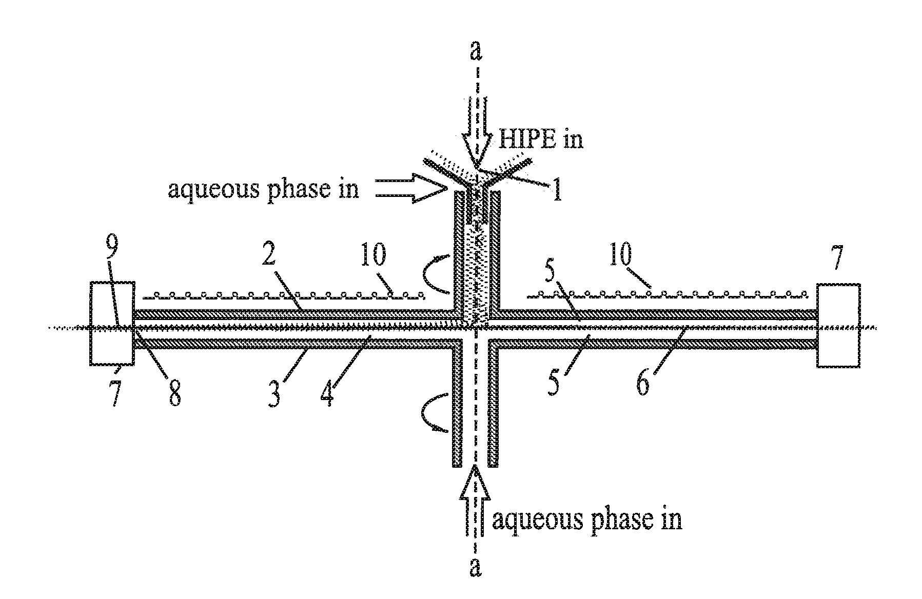
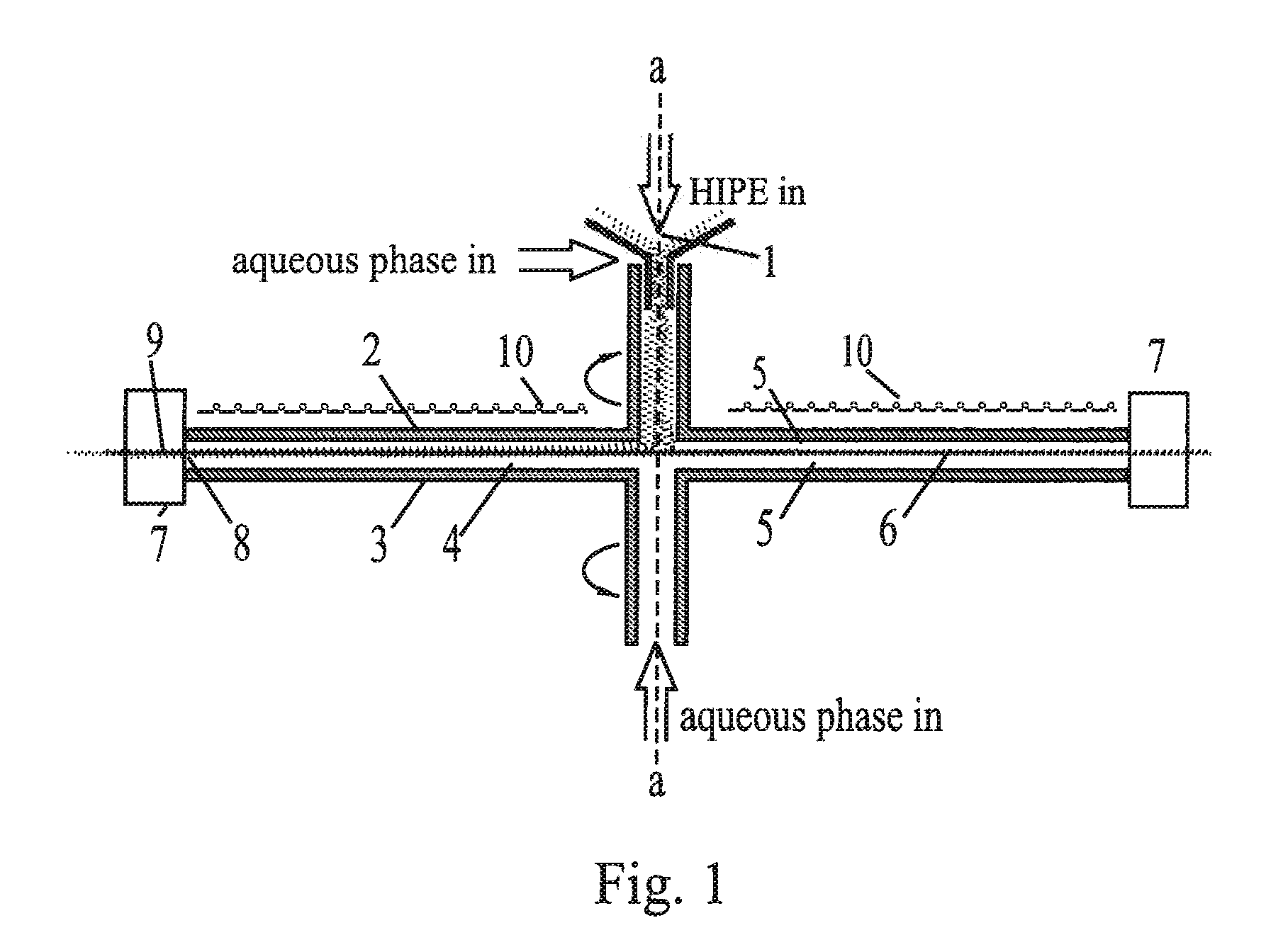
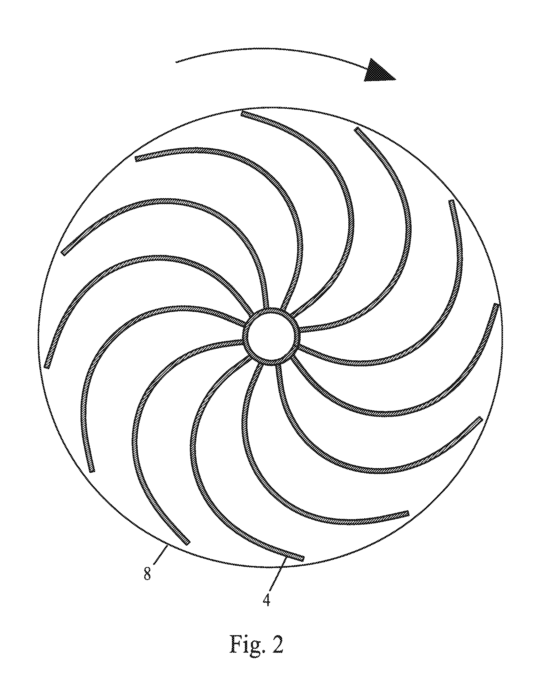
[0037]According to some embodiments, a method for forming a polymeric foam can include: axially feeding a high internal phase emulsion (HIPE) including an aqueous phase and an oil phase into a workspace defined between opposed counter-rotating centrifugal impellers having a common axis of rotation; advecting the HIPE in an orthogonal flow within the workspace away from the axis of rotation to a periphery of the workspace; curing the HIPE within the workspace to thereby form a HIPE foam at the periphery of the workspace; and withdrawing the HIPE foam through the periphery of the workspace.

[0038]In one embodiment, the HIPE foam is withdrawn through the periphery of the workspace. In another embodiment, the HIPE can be axially fed into the workspace while the HIPE foam is withdrawn. In another embodiment, however, the HIPE foam can be withdrawn when the HIPE is not axially fed into the workspace.

[0039]In one embodiment, the aforementioned method for forming a polymeric foam further inc...


PUM

PropertyMeasurementUnit
Pressureaaaaaaaaaa
Accelerationaaaaaaaaaa
Electrical conductoraaaaaaaaaa

Abstract

An RF inductor such as a Tesla antenna splices nanotube ends together to form a nanostructure in a polymer foam matrix. High Internal Phase Emulsion (HIPE) is gently sheared and stretched in a reactor comprising opposed coaxial counter-rotating impellers, which parallel-align polymer chains and also carbon nanotubes mixed with the oil phase. Stretching and forced convection prevent the auto-acceleration effect. Batch and continuous processes are disclosed. In the batch process, a fractal radial array of coherent vortices in the HIPE is preserved when the HIPE polymerizes, and helical nanostructures around these vortices are spliced by microhammering into longer helices. A disk radial filter produced by the batch process has improved radial flux from edge to center due to its area-preserving radial vascular network. In the continuous process, strips of HIPE are pulled from the periphery of the reactor continuously and post-treated by an RF inductor to produce cured conductive foam.

Description

CROSS-REFERENCE TO RELATED APPLICATIONS[0001]This application claims the benefit of U.S. Provisional Application No. 61 / 184,666 filed Jun. 5, 2009. A related pending application is U.S. application Ser. No. 11 / 893,454 filed Aug. 16, 2007, the disclosure of which is incorporated herein by reference in its entirety.BACKGROUND[0002]1. Technical Field[0003]This disclosure relates to continuous and batch manufacture of polymer emulsions such as HIPE and to use of electrical or wave energy in the RF range during the cell forming process or in physical after-treatment of a cellular product. It also relates to polycomposite polymer foams (such as, for example, carbon nanotubes in styrene or ABS monomer becoming a nanocomposite upon polymerization) and to methods of improving the strength and conductivity of polycomposite foams by linking conductive particles included therein (such as, for example, carbon nanotubes in styrene or ABS polymer) into nanostructure which increases bulk conductivi...

Claims


Application Information

Patent Timeline
IPC IPC(8): C08J9/24B01J19/00B65H69/02
CPCB01J19/20C08F2/32C08J9/0066C08J9/0071C08J9/28C08J9/228B01F7/00875B01D39/14B29C39/003B29C39/14C08J2201/028B01D33/15B01D33/21B01D33/23B01F27/412B01D39/16B01D39/1638B01D2239/025B01D2239/0258B01D39/083B01D33/70
Inventor MCCUTCHEN, WILMOT H.
Owner VORSANA INC
Why Eureka
Eureka Blog
Learn More