
Device and Method for Three-Dimensional Guidance and Three-Dimensional Monitoring of Cryoablation

Inactive Publication Date: 2010-12-02
ICECURE MEDICAL
View PDF99 Cites 43 Cited by
  • Summary
  • Abstract
  • Description
  • Claims
  • Application Information

AI Technical Summary

Benefits of technology

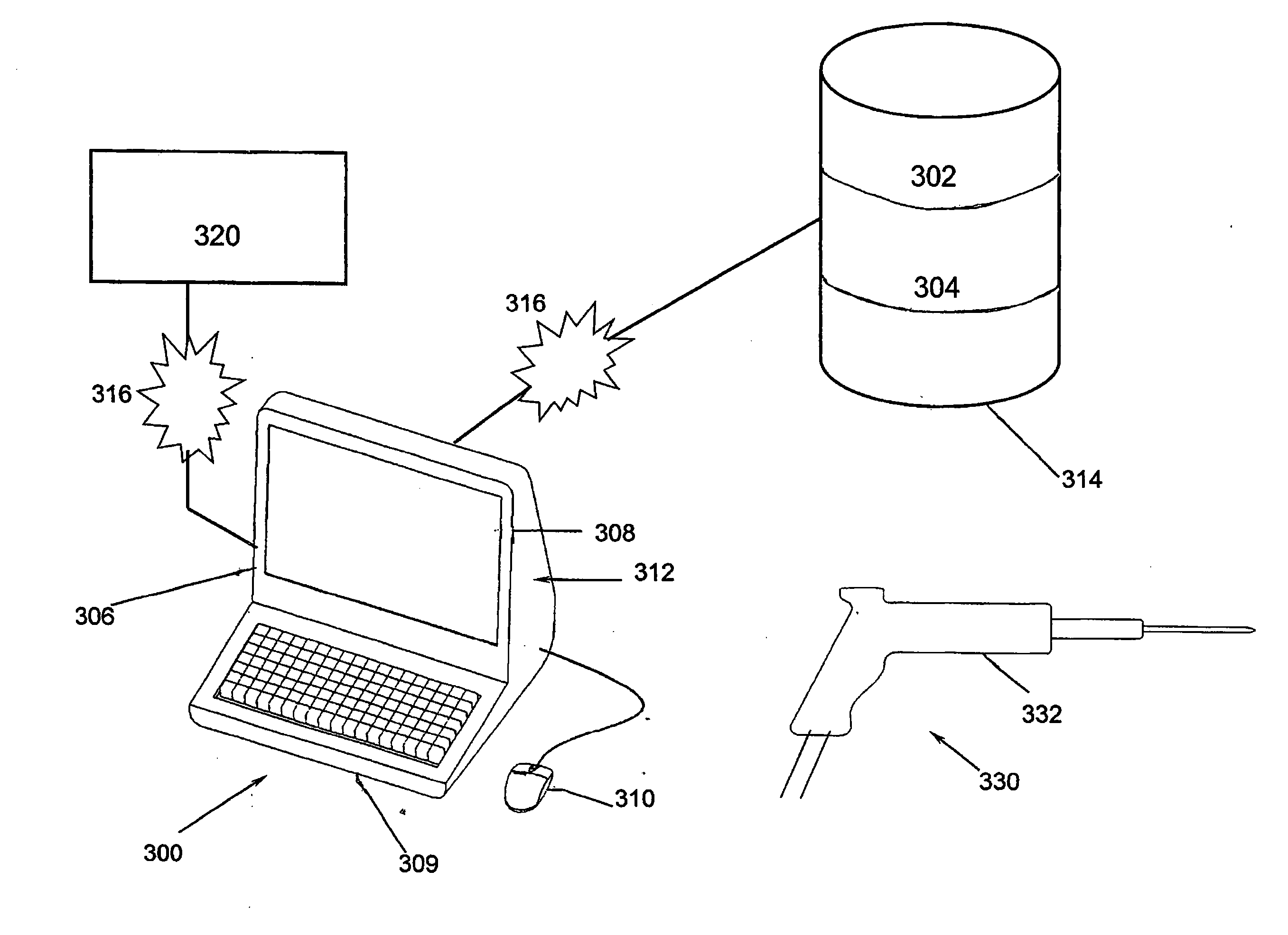
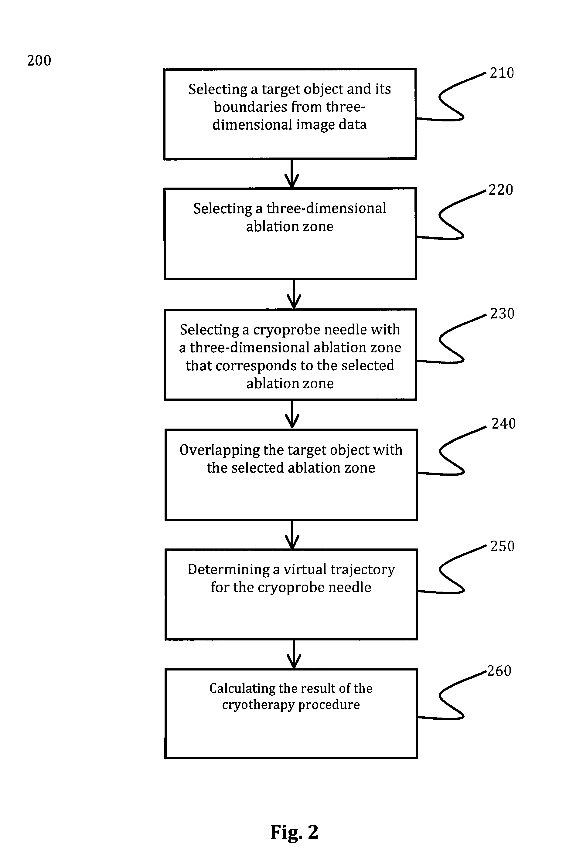
[0017]Yet another aspect of the present invention provides an improved cryotherapy method. The method preferably includes performing a cryotherapy procedure in a virtual environment by selecting a target object and its boundaries from image data, selecting a three-dimensional ablation zone, and selecting, from a library of virtual cryoprobe needles, a cryoprobe needle with a three-dimensional ablation zone that corresponds to the selected ablation zone, each virtual cryoprobe needle having a respective three dimensional ablation zone, the selected cryoprobe needle being the suitable cryoprobe needle; determining the relative location of the target object to the selected ablation zone, the location of the ablation zone encompassing the target object to the greatest extent being an optimal location; determining a trajectory for the cryoprobe needle from an entry site to the target object that brings the ablation zone of the cryoprobe needle into the optimal position by (i) calculating a main (longitudinal) axis of the cryoprobe needle, and (ii) calculating a guiding axis that extends along the main axis from the cryoprobe needle to the entry point, the guiding axis being the optimal trajectory; and calculating a result of the procedure based on the target object, the selected ablation zone, the selected needle, and optionally a duration of treatment. Then, the method receives, in real time, orientation and position information of a selected cryoprobe being used in a cryotherapy procedure, the selected cryoprobe corresponding to the identified optimal cryoprobe. Thereafter, the method displays the optimal trajectory, the received orientation information, and the received position information on the display in a manner that permits visual comparison of the orientation the cryoprobe needle to the optimal trajectory.

Problems solved by technology

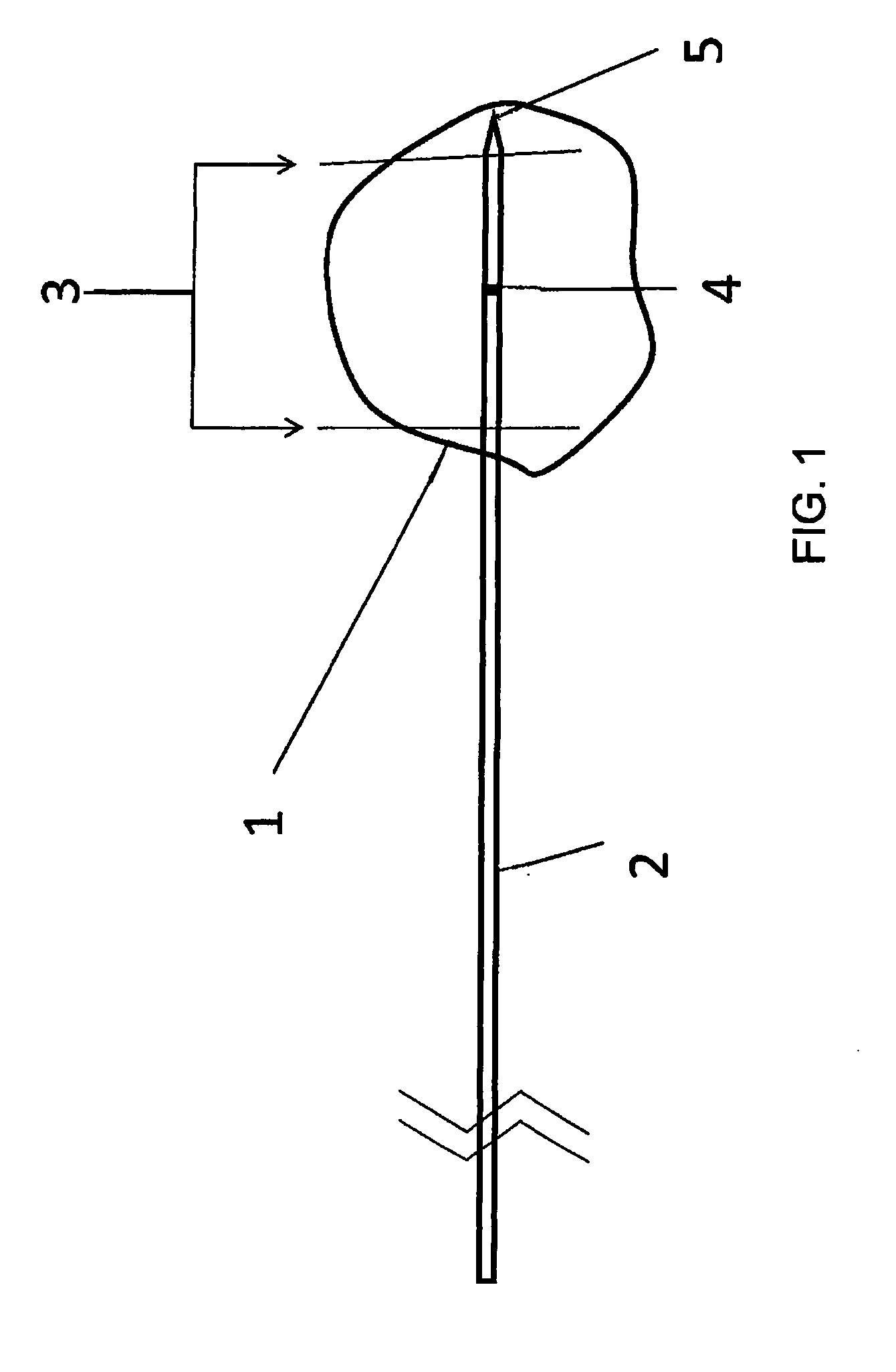
When used to treat tissue located inside of the body, administering treatment is more complex because a cryotherapy applicator or “cryoprobe”, which is a thin wand-like device, must be accurately guided, positioned and monitored to administer treatment.
Such placement, however, increases the difficulty for an operator of cryoprobe 2 to correctly place active area 3 within tumor 1.
A challenge in cryoablation is that the active area of the cryoprobe has to be placed in such a way that the target object (e.g. a tumor) is engulfed by the ablating zone to the greatest extent possible.
Also, the actual boundaries of the ablation zone within the ice-ball cannot be seen in an ultrasound.
Thus, the use of ultrasound is sometimes unsatisfactory.
The ambient temperature in the active area of the cryoprobe is extremely low (lower than −100 C), which is outside the operating range of the sensors, however.
Moving the sensors away from the active area of the probe, however, increases measurement error.
Thus, the use of electromagnetic sensors to measure the position of the active area of a cryoprobe has not been altogether satisfactory.
Another challenge in cryoablation is that the temperature around the cryoprobe tip must be accurately measured and monitored.
This approach can be undesirable because it requires the invasive placement of multiple thermocouple probes in the patient.

Method used


Image

  • Device and Method for Three-Dimensional Guidance and Three-Dimensional Monitoring of Cryoablation
  • Device and Method for Three-Dimensional Guidance and Three-Dimensional Monitoring of Cryoablation
  • Device and Method for Three-Dimensional Guidance and Three-Dimensional Monitoring of Cryoablation

Examples


Embodiment Construction

[0029]Reference will now be made in detail to embodiments of the present invention, examples of which are illustrated in the accompanying drawings, wherein like reference numerals refer to the like elements throughout. The embodiments are described below to explain the present invention by referring to the figures.

[0030]The section headings that follow are provided for ease of description only. It is to be understood that they are not intended to be limiting in any manner. Also, unless otherwise defined, all technical and scientific terms used herein have the same meaning as commonly understood by one of ordinary skill in the art to which this invention belongs. Although methods and materials similar or equivalent to those described herein can be used in the practice or testing of the present invention, suitable methods and materials are described below. In case of conflict, the patent specification, including definitions, will control. In addition, the materials, methods, and examp...


PUM


Abstract

Systems and methods for three-dimensional guidance and monitoring of a cryotherapy procedure, including virtually performing the procedure. A method of virtually performing a cryotherapy procedure includes: selecting a target object from three-dimensional image data displayed in three dimensions; selecting a three-dimensional ablation zone; selecting, from a library of virtual cryoprobe needles, a cryoprobe needle with a three-dimensional ablation zone that corresponds to the selected ablation zone; comparing the location of the target object with the selected ablation zone, the location of the ablation zone encompassing the target object to the greatest extent being an optimal location, determining, via a processor, a virtual trajectory for the virtual cryoprobe needle from an entry site to the target object when the ablation zone of the virtual cryoprobe needle is in the optimal position; and calculating a result of the procedure based on the target object, the selected ablation zone, the selected needle, and a duration of treatment. Guidance may also optionally be provided during an actual cryotherapy procedure, based upon three dimensional image data and / or data from one or more sensors, for example according to the results of the virtual cryotherapy procedure.

Description

BACKGROUND[0001]1. Field of the Invention[0002]Embodiments of the present invention relate generally to cryotherapy and, more particularly, to image guided cryotherapy systems and methods.[0003]2. Description of Related Art[0004]Generally, cryotherapy, also called cryoablation, is a relatively minimally invasive treatment that uses extreme cold to freeze and destroy diseased tissue, such as cancer cells. Because cryotherapy tend to be minimally invasive, cryotherapy can be particularly useful in treating tumors that make surgical resection difficult, such as cancers of the prostate, liver, and cervix, for example.[0005]Cryotherapy can be used to treat tissue located both outside and inside of a patient. When used to treat tissue located outside of the body, cryoablation may be achieved by the topical application of a cooling agent via a cotton swab or a spray device. When used to treat tissue located inside of the body, administering treatment is more complex because a cryotherapy a...

Claims


Application Information

Patent Timeline
IPC IPC(8): A61B8/00A61B18/02G09B23/28
CPCA61B18/02A61B2034/2051A61B2090/378A61B34/20
Inventor SHAI, EYALSHARON, SHIMONBERZAK, NIR
Owner ICECURE MEDICAL
Learn More