Assembly and a method for in situ processing of waste

a technology of in situ processing and waste, which is applied in the direction of biochemistry equipment, biochemistry equipment and processes, solid separation, etc., can solve the problem that nothing more can be done on the site, and achieve the effect of convenient disassembly

Inactive Publication Date: 2010-12-02
MPI - MANAGEMENT
View PDF1 Cites 2 Cited by
  • Summary
  • Abstract
  • Description
  • Claims
  • Application Information

AI Technical Summary

Benefits of technology

[0015]By means of the devices and by continuous monitoring of the waste flow set in motion, it is possible to react immediately to components and substances present in the waste flow. Refuse dumps are often found to contain a high concentration of relatively valuable residual materials. By means of the control device, it is furthermore possible to control the end products in such a way that the financial return can be maximized. Moreover, continuous control of the processed flow is possible, also for a supervisor / authority having to supervise responsible processing.
[0016]The processing devices make it possible to vary the processing capacity and adapt it to a situation, in other words, inter alia, to vary the compositions and quantities of the various flows and the desired end products or proportion of end products.
[0018]Subclaims 2-8 deal with interconnections in the assembly making it possible to use products obtained in one part of the assembly as fuel in another part of the assembly, and in particular under the control of the control device.
[0020]According to claim 9, one or more of the processing devices—in particular all processing devices—and / or the generator unit and / or the incinerators are made up of modules that can be disassembled and reassembled, which modules can be transported by road on a vehicle such as a low loader or truck. The assembly according to the invention is therefore easy to disassemble after the work has been carried out in situ, and is easy to move to another site, construct at that other site and use at that other site for the in situ processing of waste there. This is of great benefit particularly for cleaning up waste disposal sites.

Problems solved by technology

However, because of the presence of the waste, nothing more can be done with the site.

Method used


Image

  • Assembly and a method for in situ processing of waste
  • Assembly and a method for in situ processing of waste
  • Assembly and a method for in situ processing of waste

Examples


Embodiment Construction

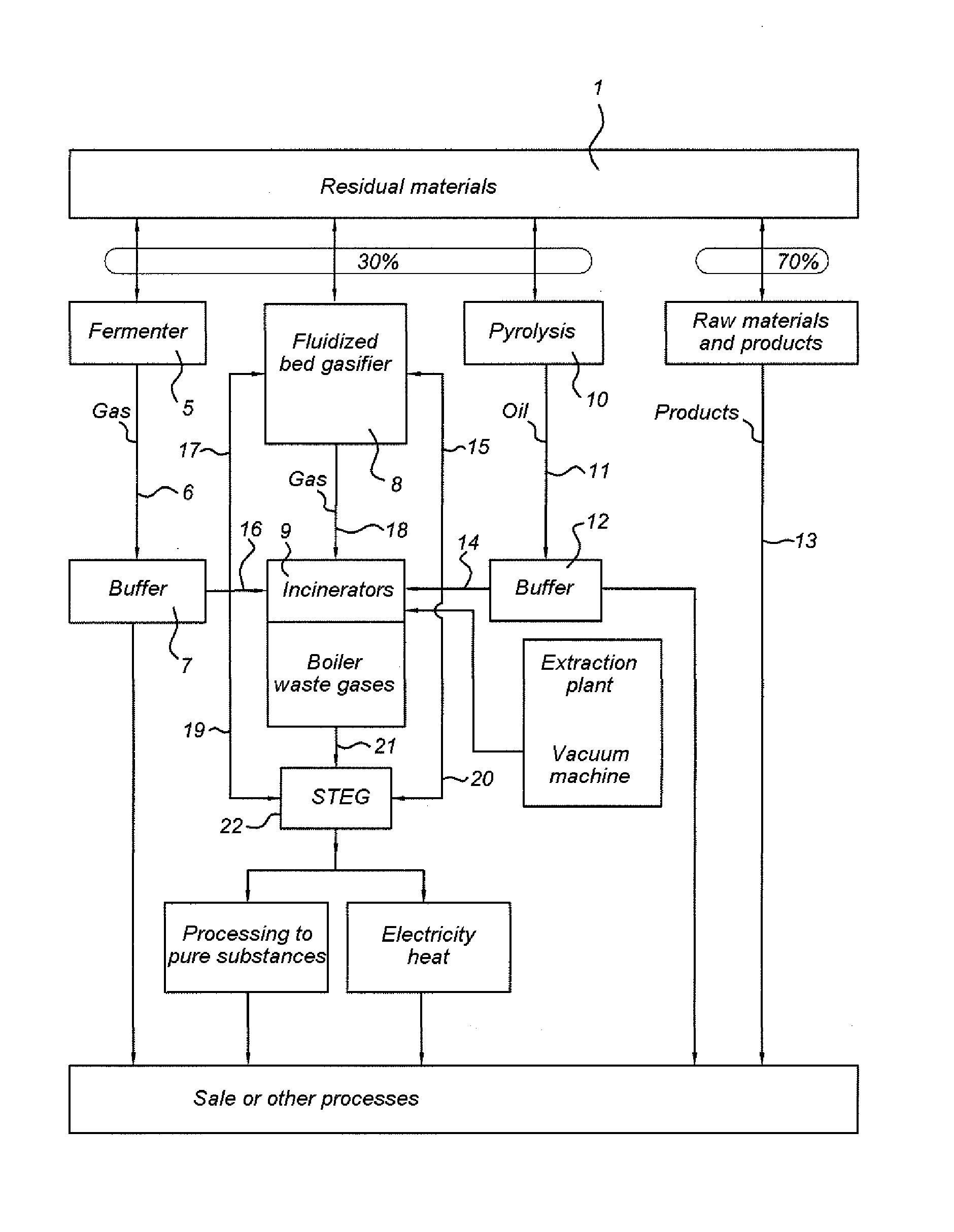
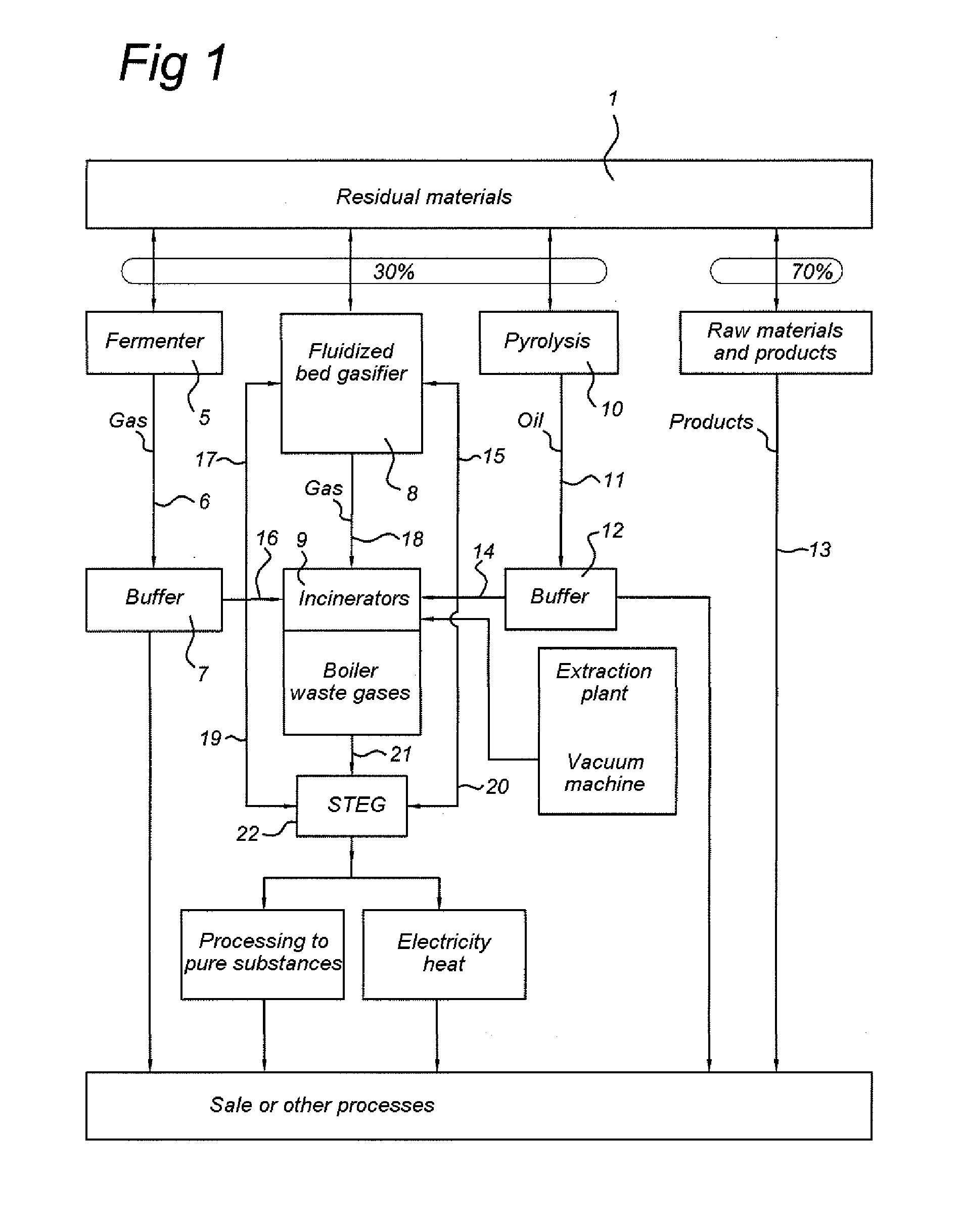
[0033]FIG. 1 shows an embodiment of an assembly for the in situ processing of waste or for cleaning up a waste disposal site according to one embodiment of the invention. The waste disposal site or the flow of waste is set in motion by means of, for example, an excavator or other devices which excavate a refuse dump and convert it into a flow of material which is fed to a sorting device 1.

[0034]The sorting device 1 can be composed of one or more of the following interconnected components, such as, for example, one or more: Rotamill excavator(s); shovel(s); shovel loader(s); dumper truck(s), such as the Volvo BM type, conveyor belts; Powerscreen GAOF screen(s); vibrating conveyor(s), for example one or more octagonal drum screens, one or more round drum screens, one or more flat vibrating screens; magnetic separator(s); wind shifter(s); air jet separator(s) (also referred to as airjets); low-pressure cold washer(s); low-pressure hot washer(s); high-pressure steam washer(s); high-pres...


PUM


Abstract

The invention relates to a device and a method for the in situ processing of waste, in particular for cleaning up a waste disposal site. The device comprises a sorting device with a set of processing devices connected downstream of said device. This set of processing devices comprises a fermenting device, a fluidized bed gasifier, and a pyrolysis device. Furthermore, the assembly comprises a control device for controlling and measuring the various material flows.

Description

BACKGROUND OF THE INVENTION[0001]The invention relates to assembly and method for the in situ processing of waste.[0002]In particular, the assembly and method is suitable for cleaning up a waste disposal site or former waste disposal site.[0003]Such an approach to current and former waste disposal sites has not been known or applied until now.[0004]Former waste disposal sites in particular are often situated in locations and places that are very suitable for other purposes, such as residential building or industrial development. However, because of the presence of the waste, nothing more can be done with the site.SUMMARY OF THE INVENTION[0005]The object of the invention is to provide an assembly and a method for restoring to a usable state ground area that is currently or was formerly used as a waste disposal site.[0006]A further object of the invention is to perform such restoration in an environmentally sound manner, without emission of harmful substances, and without such harmful...

Claims


Application Information

Patent Timeline
IPC IPC(8): B09B3/00
CPCB03B9/06B09B1/00B09B3/00Y02W30/38Y02W30/30
Inventor KOENS, ANTONIUS DOROTHEUS
Owner MPI - MANAGEMENT
Why Eureka
Try Eureka