Switching mode power supply with a spectrum shaping circuit

a spectrum shaping circuit and power supply technology, applied in the direction of power conversion systems, dc-dc conversion, instruments, etc., can solve the problems of large harmonic gain, increased electromagnetic interference (emi) of the overall system, and harmonic gain caused by switching frequency, so as to reduce electromagnetic interference

Active Publication Date: 2010-12-02
MONOLITHIC POWER SYST
View PDF11 Cites 17 Cited by
  • Summary
  • Abstract
  • Description
  • Claims
  • Application Information

AI Technical Summary

Benefits of technology

The present invention relates to a method for controlling the output voltage from a switched-mode power source which reduces electro magnetic interference (EMI) during operation. This is achieved by creating a timed sequence with variable frequencies that affects the performance of the transformation process used to produce the desired output voltage. By measuring these changes and adjusting the rate at which the transformation takes place through a controlled switching mechanism, EMI can be minimized while still achieving optimal efficiency.

Problems solved by technology

The technical problem addressed in this patent is how to design a switching mode power supply that operates at high frequencies while reducing electromagnetic interference.

Method used


Image

  • Switching mode power supply with a spectrum shaping circuit
  • Switching mode power supply with a spectrum shaping circuit
  • Switching mode power supply with a spectrum shaping circuit

Examples


Embodiment Construction

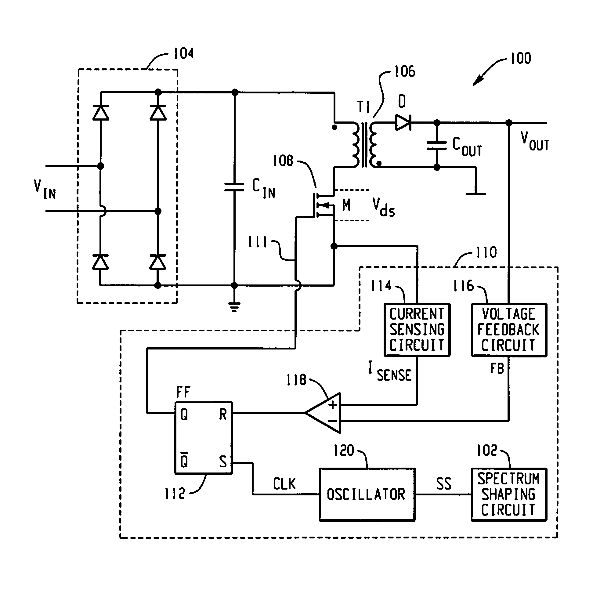
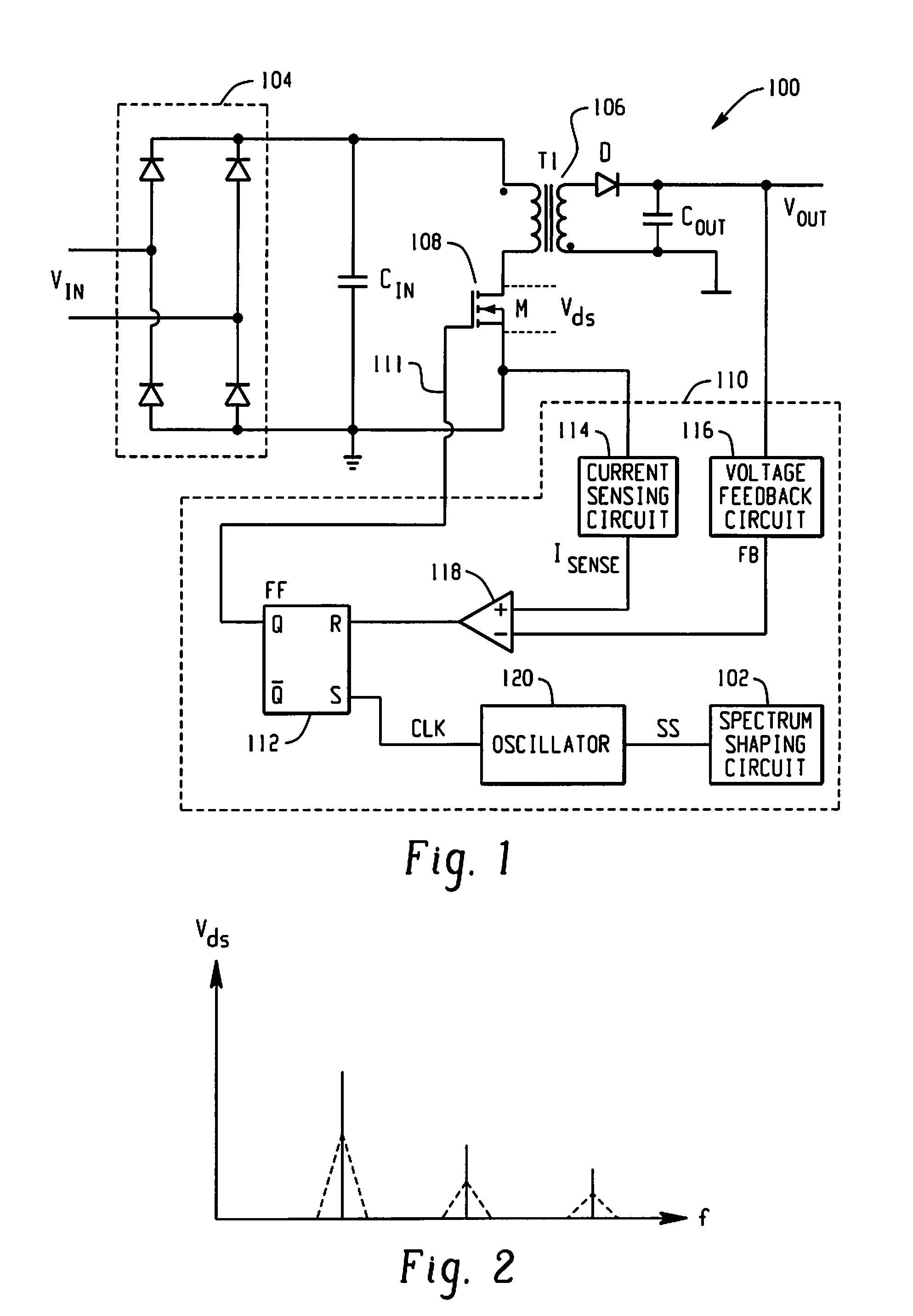
[0020]FIG. 1 is a diagram of an example switching mode power supply 100 having a spectrum shaping circuit 102. The switching mode power supply 100 includes a rectifier bridge 104, a transformer 106, a switching circuit 108, and a switching control circuit 110. In operation, the rectifier bridge 104 receives an AC input voltage (Vin) that it converts to a DC input voltage received by the primary winding of the transformer 106. The transformer 106 is controlled by the switching circuit 108 to generate a DC output voltage (Vout) on the secondary winding. The switching circuit 108, which may include a MOSFET (as illustrated), or some other suitable electronic switching device, controls the current flow through the primary winding of the transformer 106 to effectively switch the transformer 106 on and off. Also illustrated in FIG. 1 is an input capacitor (Cin) that stores the DC input voltage, an output capacitor (Cout) that stores the DC output voltage, and a diode (D) that prevents cur...


PUM


Abstract

In accordance with the teachings described herein, systems and methods are provided for a switching mode power supply. In one example, the switching mode power supply may include a transformer, a switching circuit and a switching control circuit. The transformer receives a DC input voltage on a primary winding and generates a DC output voltage on a secondary winding. The switching circuit, which may include a MOSFET switch, is coupled to the transformer and is configured to switch the transformer on and off. The switching control circuit generates a switching control signal to control the switching circuit in order to regulate the DC output voltage of the transformer. The switching control circuit is configured to generate the switching control signal as a function of a timing signal having a varying frequency, wherein the varying frequency of the timing signal causes a switching frequency of the switching circuit to vary over a period of time in order to reduce electromagnetic interference caused by the switching circuit.

Description


Claims


Application Information

Patent Timeline
Owner MONOLITHIC POWER SYST
Why Eureka
Try Eureka