


Quick Research
Generate reliable direction feasibility study reports for your R&D in just a few steps.

Technical Q&A
Discover and master advanced knowledge NOW. Basics, ideas, possibilities, all at once.

Find Solutions
As an expert in R&D theories, this can generate solutions to your technical problems instantly.

Evaluate Feasibility
Analyze your overall solution with one click, know your potential R&D risks in advance.

Monitor Landscape
Get weekly tech updates, stay abreast of the latest tech innovations and key insights.
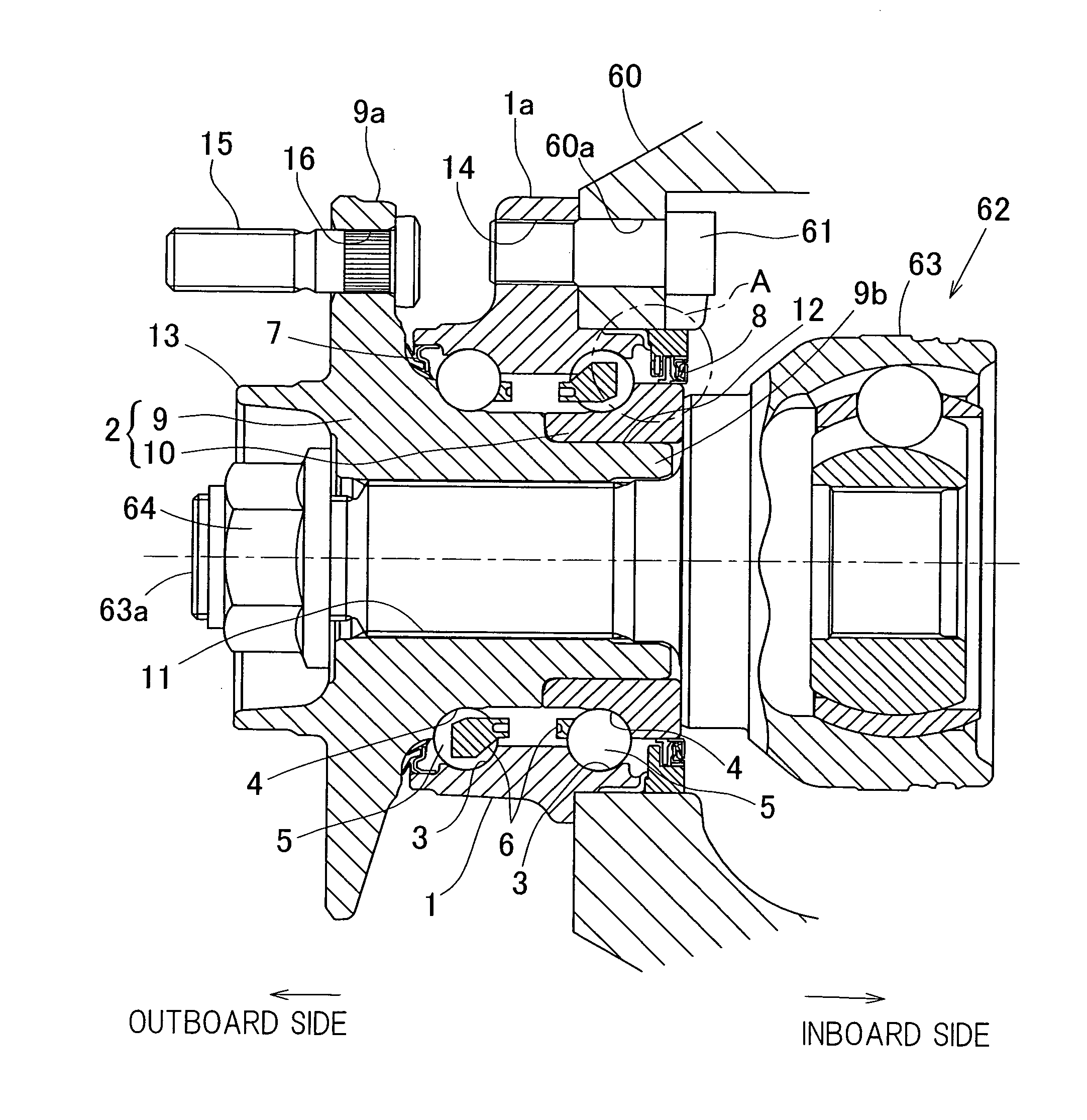
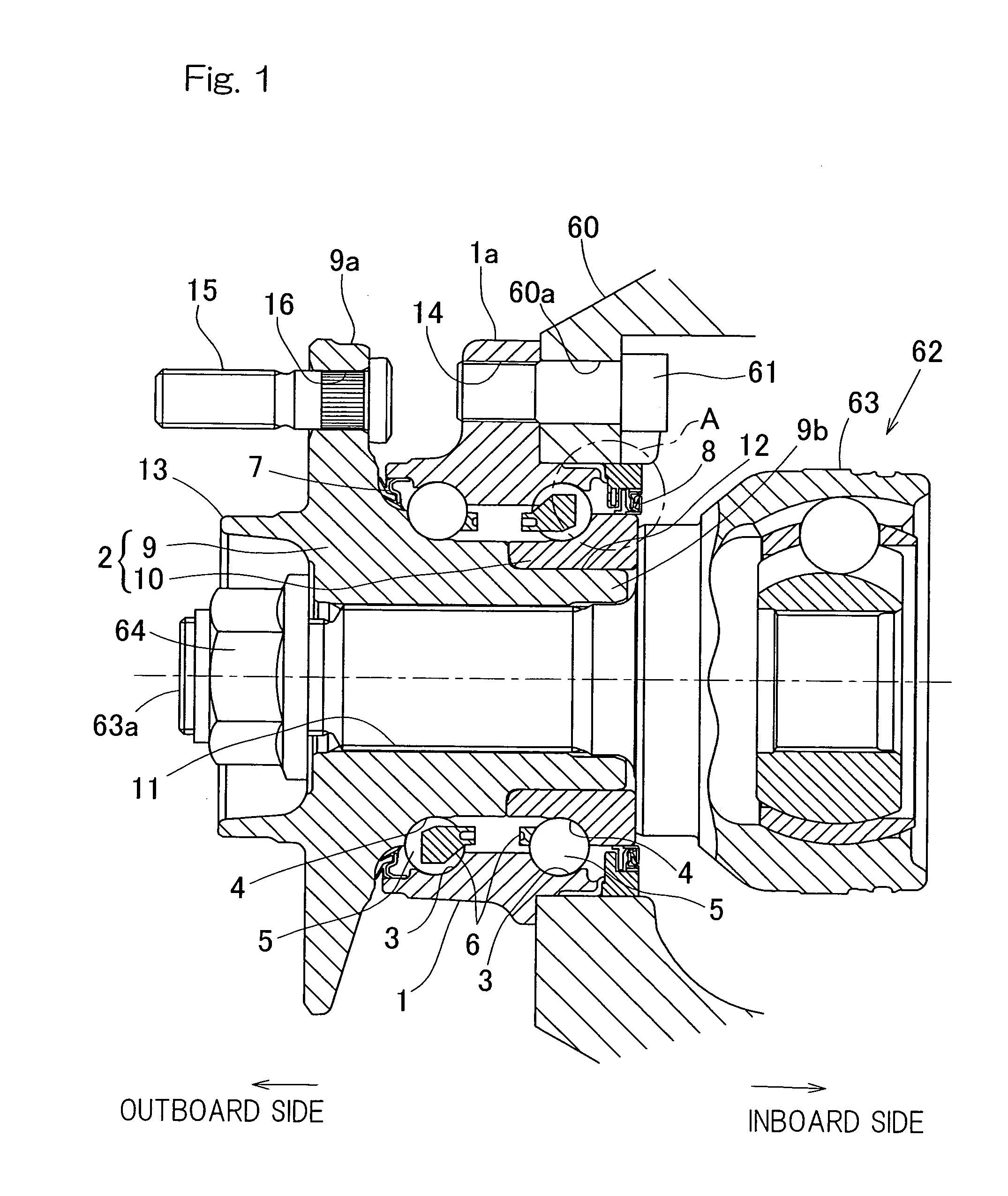
Wheel bearing device with rotation detector
a technology of rotation detector and bearing, which is applied in the direction of mechanical equipment, instruments, transportation and packaging, etc., can solve the problems of affecting the compactification effect, the device failing to accurately, and the magnetic encoder being easily swollen
- Summary
- Abstract
- Description
- Claims
- Application Information
AI Technical Summary
Benefits of technology
Problems solved by technology
Method used
Image

Examples
first embodiment
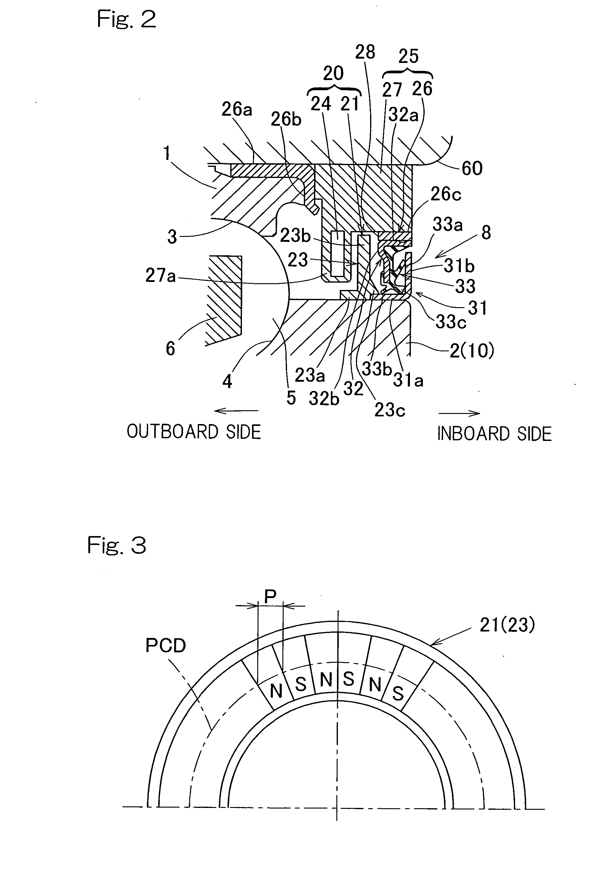
[0063]Also, since the plastic magnetic encoder 21 and the sealing unit 8 are positioned axially outwardly relative to a built-in portion of the magnetic sensor 24 of the sensor holder 25, the plastic magnetic encoder 21 and the sealing unit 8 together can be assembled after the sensor holder 25 has been fitted to the outer member 1 when the rotation detector 20 is assembled in the wheel support bearing assembly. In other words, if the magnetic encoder is positioned axially inwardly of the magnetic sensor 24 in a manner converse to that described above, that assemblage would require a three step work of incorporating the magnetic encoder, the sensor holder and the sealing unit, but in the practice of the first embodiment described above, only two steps are required to incorporate the sensor holder 25 and to incorporate a subassembly of the magnetic encoder 21 and the sealing unit 8. For this reason, the assemblability of the rotation detector equipped wheel support bearing assembly i...
third embodiment
[0071]As is the case with any of the previously described embodiments of the present invention, even the rotation detector equipped wheel support bearing assembly according to this third embodiment makes use of the sealing unit 8 for sealing the space delimited between the sensor holder 25 and the inner member 2 and, therefore, the plastic magnetic encoder 21 can be prevented from being work by external foreign matters.
[0072]FIG. 6 illustrates a fourth embodiment of the present invention. According to this fourth embodiment, the plastic magnetic encoder 21B, which has been shown and described as employed in the rotation detector equipped wheel support bearing assembly according to the third embodiment shown in FIG. 3 and which is comprised of the composite of the slinger 22 and the plastic multipolar magnet 23, is replaced with the plastic magnetic encoder, now identified by 21C, which is comprised solely of the plastic multipolar magnet 23. The plastic multipolar magnet 23 is of an...
fifth embodiment
[0075]In this fifth embodiment, the sensor embedding projection 27a in the sensor holding body 27 of the sensor holder 25 is of such a design that a corner portion delimited between a tip surface thereof and the bearing inner surface is rendered to be an inclined face parallel to the inclined face 23b of the magnetic encoder 21D and the magnetic sensor 24 is built in and arranged along this inclined face.
[0076]As is the case with any one of the various embodiments of the present invention hereinabove described, even in this rotation detector equipped wheel support bearing assembly, the use is made of the sealing unit 8 for sealing the space delimited between the sensor holder 25 and the inner member 2 at the bearing outer position outwardly of the plastic magnetic encoder 21D and, therefore, the plastic magnetic encoder 21D can be prevented from being worn by the external foreign matters.
[0077]Also, since the plastic magnetic encoder 21D can be designed to have a schematic sectional...
PUM
| Property | Measurement | Unit |
|---|---|---|
| melting viscosity | aaaaa | aaaaa |
| melting viscosity | aaaaa | aaaaa |
| melting viscosity | aaaaa | aaaaa |
Abstract
Description
Claims
Application Information
 - R&D Engineer
- R&D Manager
- IP Professional
- Industry Leading Data Capabilities
- Powerful AI technology
- Patent DNA Extraction
Browse by: Latest US Patents, China's latest patents, Technical Efficacy Thesaurus, Application Domain, Technology Topic, Popular Technical Reports.
© 2024 PatSnap. All rights reserved.Legal|Privacy policy|Modern Slavery Act Transparency Statement|Sitemap|About US| Contact US: help@patsnap.com