Clean feet foot wash

Inactive Publication Date: 2010-12-02
SHAPIRO ELI MINIER
View PDF15 Cites 18 Cited by
  • Summary
  • Abstract
  • Description
  • Claims
  • Application Information

AI Technical Summary

Benefits of technology

[0013]It is an object of the clean feet foot wash to provide a water reservoir for storing water that may not be available at the location where the foot was is being used. The water storage tank can be connected to an available fresh water storage tank or a separate or an existing water tank. Typically this water supply has little or no pressure to create flow of any velocity. The water can be recycled to minimize water use using a simple filter mechanism to strain sand or debris from the reclaimed water. The filter can be a simple mesh or metal strainer where the debris is easily discarded. If a larger amount of water is available the sand and debris can be drained from the foot wash and not recycled.
[0014]It is an object of the clean feet foot wash to provide a pump to increase the amount of pressure for the water that is being used to wash feet. This water pump is connected to the water storage tank and can either be a separate water pump or can connect to an existing pump. The pump can be used to further increase the water pressure to increase the spraying / washing pressure.
[0015]It is an object of the clean feet foot wash to use air in combination with the water. An air compressor is used to increase the velocity of the water being used and also to provide some drying to the feet. The air can be stored in an air tank to increase the volume of air that is quickly available. The air pump can operate with a lower power requirement to store air when the wash is not being used. It is also contemplated that a vacuum system can be incorporated to increase the velocity of water being sprayed. The vacuum can also be used to assist in drying wet feet.
[0017]It is still another object clean feet foot wash for the spraying jets to exist both on the outsides of the feet as well as between the feet. This allows the foot washer to spray all around the feet and wash debris into the bottom of the washer and ensures a more complete wash without removing just the sand or debris from the outer legs and outsides of the feet.

Problems solved by technology

The device further uses water from a hose and does not utilize air to promote drying.

Method used


Image

  • Clean feet foot wash
  • Clean feet foot wash
  • Clean feet foot wash

Examples


Embodiment Construction

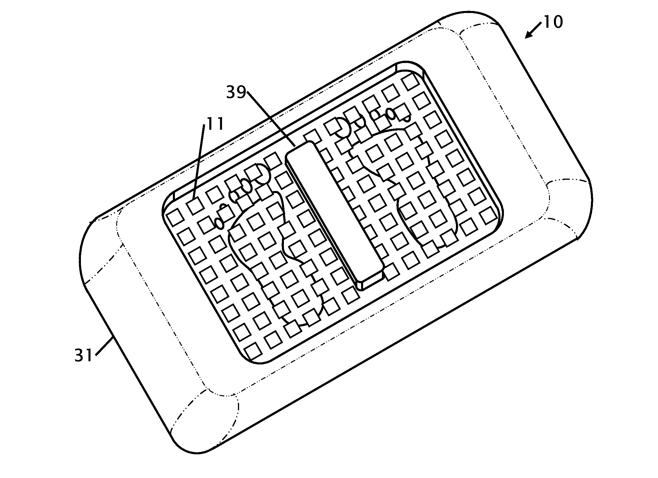
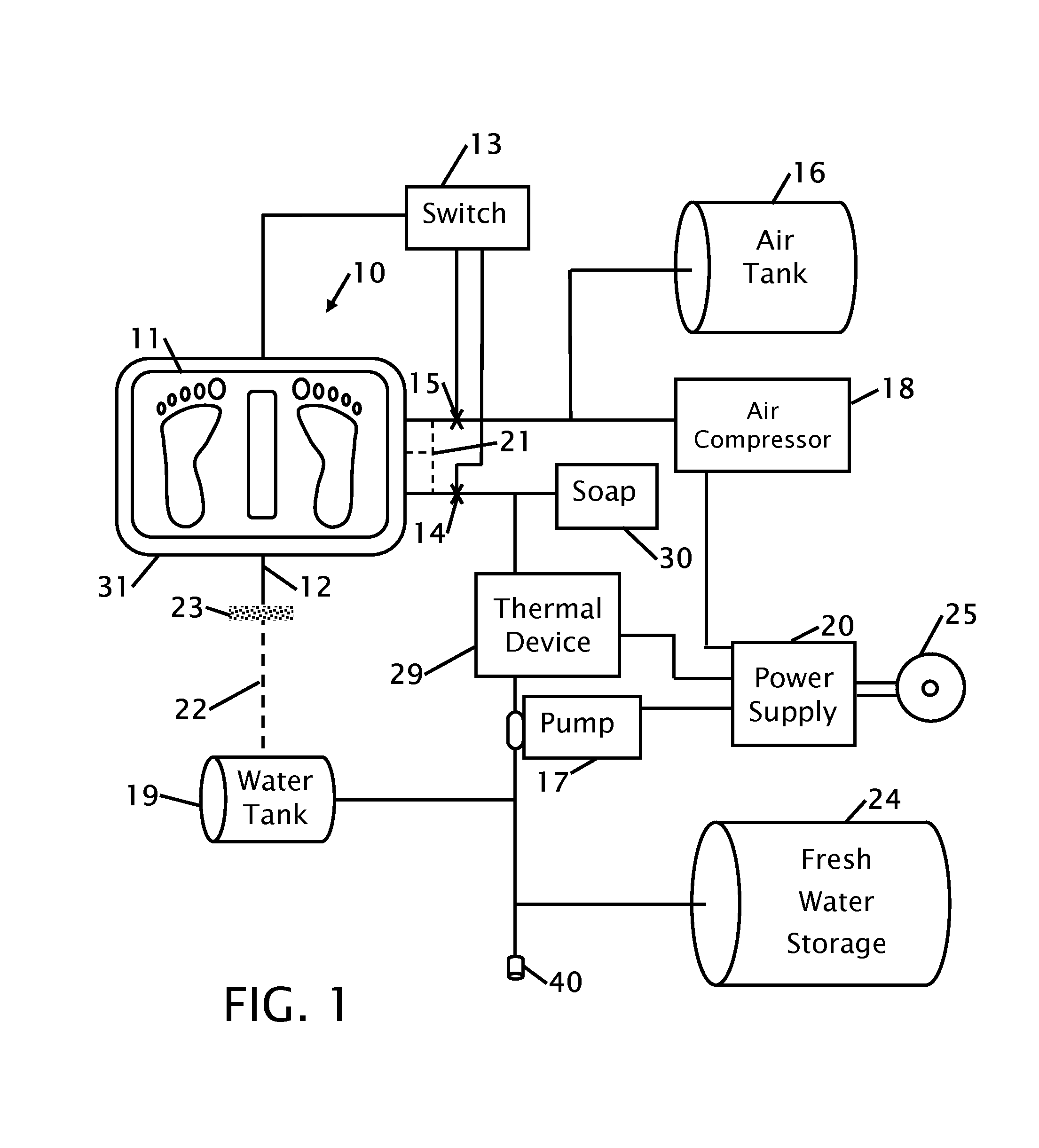
[0027]FIG. 1 shows a block diagram of the foot washing device 10. The foot washing device has a step pad or platform 11 in a basin 31 that is shown and described in FIGS. 2-8. The device is self contained where some or all of the components are enclosed within the basin. These components are shown in the block diagram outside of the basin, but are preferably enclosed within or in the underside of the basin. In general when sufficient weight is placed on the step pad 11 the weight activates a switching mechanism 13 that activates the device 10. The switch 13 opens a water valve 14 and or an air valve 15. In one embodiment the air and water flow through different lines into the basin 31. In an alternative embodiment the water and air lines are combined 21 where they flow into the basin 31.

[0028]The device 10 can be self contained with a power supply 20 such as a battery or can be powered from an external power supply 25. The external power supply 25 can charge the power supply 20 (bat...


PUM


Abstract

Improvements in a foot washing device is disclosed. The improvements include the use of air with water to increase the washing efficiency with minimal use of water. The device is ideally used where clean water is limited such as on a boat, ship or other device where a person enters the boat with sand dirt or debris on not only the bottom but also the sides and top of the feet. The device blows water and air over the top of the feet and under the feet to wash off the sand. The amount of cleaning force is critical to reduce sand that can leave the feet and enter into the boat. The water can be filtered and recycled to reduce clean water use. The device may further include its own power supply, chemical cleaning agent and a water heating or cooling mechanism.

Description

CROSS REFERENCE TO RELATED APPLICATIONS[0001]This application is a continuation-in-part of applicant's co-pending application Ser. No. 61 / 181,257 filed May 26, 1009 the entire contents of which is hereby expressly incorporated by reference herein.STATEMENT REGARDING FEDERALLY SPONSORED RESEARCH OR DEVELOPMENT[0002]Not ApplicableTHE NAMES OF THE PARTIES TO A JOINT RESEARCH AGREEMENT[0003]Not ApplicableINCORPORATION-BY-REFERENCE OF MATERIAL SUBMITTED ON A COMPACT DISC[0004]Not ApplicableBACKGROUND OF THE INVENTION[0005]The removal of sand from feet is important to minimize damage to the carpeting and deck of a boat. In some locations, such as on the ocean, the supply of clean water is limited and while there may be water that is available around a boat the quality of the water is often questionable. To minimize the amount of water that is being used and to optimize the velocity of the limited water that is being sprayed, the water is supplemented with air pressure or a vacuum to incre...

Claims


Application Information

Patent Timeline
IPC IPC(8): A47K3/022
CPCA47K7/04A47K3/022
Inventor SHAPIRO, ELI MINIER
Owner SHAPIRO ELI MINIER
Why Eureka
Try Eureka