Gas Supply Apparatus With Improved Control

Active Publication Date: 2010-11-25
DEVX TECH IP
View PDF14 Cites 1 Cited by
  • Summary
  • Abstract
  • Description
  • Claims
  • Application Information

AI Technical Summary

Benefits of technology

[0039]Thus, the present invention also removes a constraint from the design of the mixing valve, namely that it can supply enough air from the secondary supply of the gas mixer to the outlet junction as may be required. If the gas supply apparatus is supplying hypoxic air to a subject, they will be supplied enough air, through the tertiary supply valve, even though the most efficient or economical choice of gas mixer may not supply sufficient air from the secondary supply once the primary supply has been shut-off.
[0044]If nitrogen at the first supply is suspended, the outlet junction is supplied with a combination of normoxic air at the third supply and hypoxic air from the reservoir. This combination is immediately less hypoxic than the mix previously delivered from the gas mixer. This combination then gradually becomes less hypoxic as the reservoir of hypoxic air is depleted. Eventually only normoxic air, from the third supply via the alternative supply gas valve, is available at the outlet junction. A gradual transition from hypoxic to normoxic air mitigates a tendency of the mammalian body to overcompensate, or ‘bounce’ its blood saturation levels. This allows improved effectiveness of hypoxic training that may utilise the gas supply apparatus.
[0060]Preferably, the controller is adapted to reduce the oxygen content of gas if the first predetermined level is not reached within the predetermined time interval.
[0063]Preferably, the controller is adapted to increase the oxygen content of gas delivered at the reservoir if the second predetermined time interval has been reached within the second predetermined time interval.
[0099]Preferably, pulse width modulation of each of the valves included with primary and secondary inlets allows control of the total flow through the venturi as well as control of the mix of nitrogen and air exiting the outlet.
[0105]Preferably, one of the first or second degrees of restriction may substantially prevent any flow of gas through the control chamber.

Problems solved by technology

If the gas supply apparatus is supplying hypoxic air to a subject, they will be supplied enough air, through the tertiary supply valve, even though the most efficient or economical choice of gas mixer may not supply sufficient air from the secondary supply once the primary supply has been shut-off.

Method used


Image

  • Gas Supply Apparatus With Improved Control
  • Gas Supply Apparatus With Improved Control
  • Gas Supply Apparatus With Improved Control

Examples


Embodiment Construction

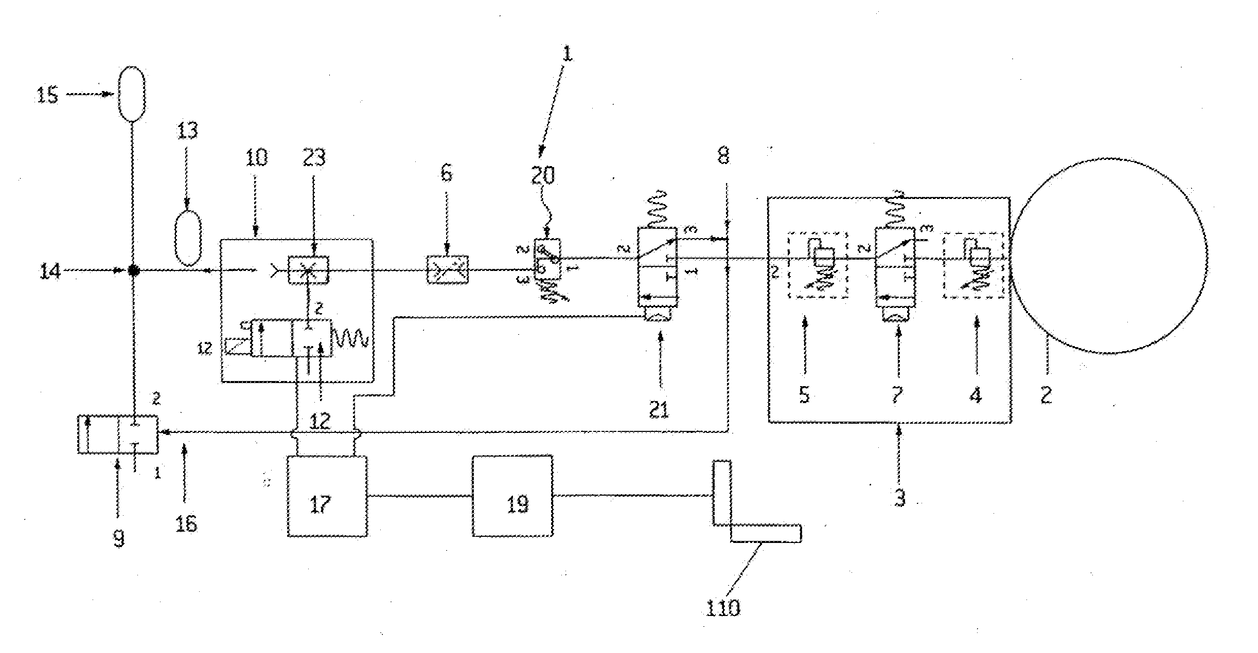
[0135]FIG. 1 is a schematic diagram of a pneumatic circuit 1 of a hypoxic training apparatus according to a preferred embodiment of the present invention.

[0136]The circuit 1 is supplied with a pressurised fluid, in this case nitrogen gas N2, from the gas cylinder 2.

[0137]The gas cylinder 2 feeds a pressure regulator stage 3. This stage may have a pair or series of pressure regulators 4, 5 to regulate, the pressure precisely even over the wide range of pressures of a nitrogen bottle at various stages of fill. Typically, the pressure in a nitrogen bottle may vary from 140 bar (full) to 2 bar (empty). A nitrogen generator could be substituted for the gas cylinder 2.

[0138]The regulator stage 3 has an on / off valve 7 which is preferably located between the regulators 4 and 5. The regulator stage 7 feeds a flow control valve 6 via on / off valve 21 and pressure switch 20. If a supply stage on / off valve 7 of suitable maximum flow rate is used, the flow valve 6 may possibly be eliminated. The ...


PUM


Abstract

A gas supply apparatus with improved control is provided. The gas supply apparatus provides gas at an outlet junction. The apparatus includes a gas mixer for gasses from primary and secondary supplies to a given ratio. The apparatus also includes a gas reservoir supplied by the gas mixer. A tertiary supply valve is also included and connected in parallel with the reservoir. The tertiary supply valve is adapted to connect the outlet junction to a tertiary gas supply when gas is not being supplied to a mixer by the primary and / or secondary supply.

Description

FIELD OF THE INVENTION[0001]The present invention relates to apparatus for supplying a variable mix of gases. In particular it relates to apparatus for supplying a variable mix of breathable gases. Further in particular it relates to an apparatus for supplying a subject with gas having a variable level of oxygen. Yet further in particular it relates to an apparatus for applying hypoxic training to a subject.DESCRIPTION OF THE PRIOR ART[0002]Hypoxic training involves supplying a subject with hypoxic air to place a beneficial stress on the subject's pulmonary system. Generally this type of training is applied intermittently to allow the subject to recover from the stress by breathing normoxic air.[0003]In this context, hypoxic air is air with a modified oxygen content and normoxic air is ambient atmospheric air. Hypoxic air has reduced oxygen levels compared to normoxic air.[0004]The benefits of hypoxic training were discovered by observation of the physiology of subjects living in a ...

Claims


Application Information

Patent Timeline
IPC IPC(8): G09B9/00A61M16/12
CPCA61M16/0075A63B2213/006A61M16/12
Inventor CHAPMAN, ANDREW MICHAELPOTTER, BRUCE WILLIAM
Owner DEVX TECH IP
Why Eureka
Try Eureka