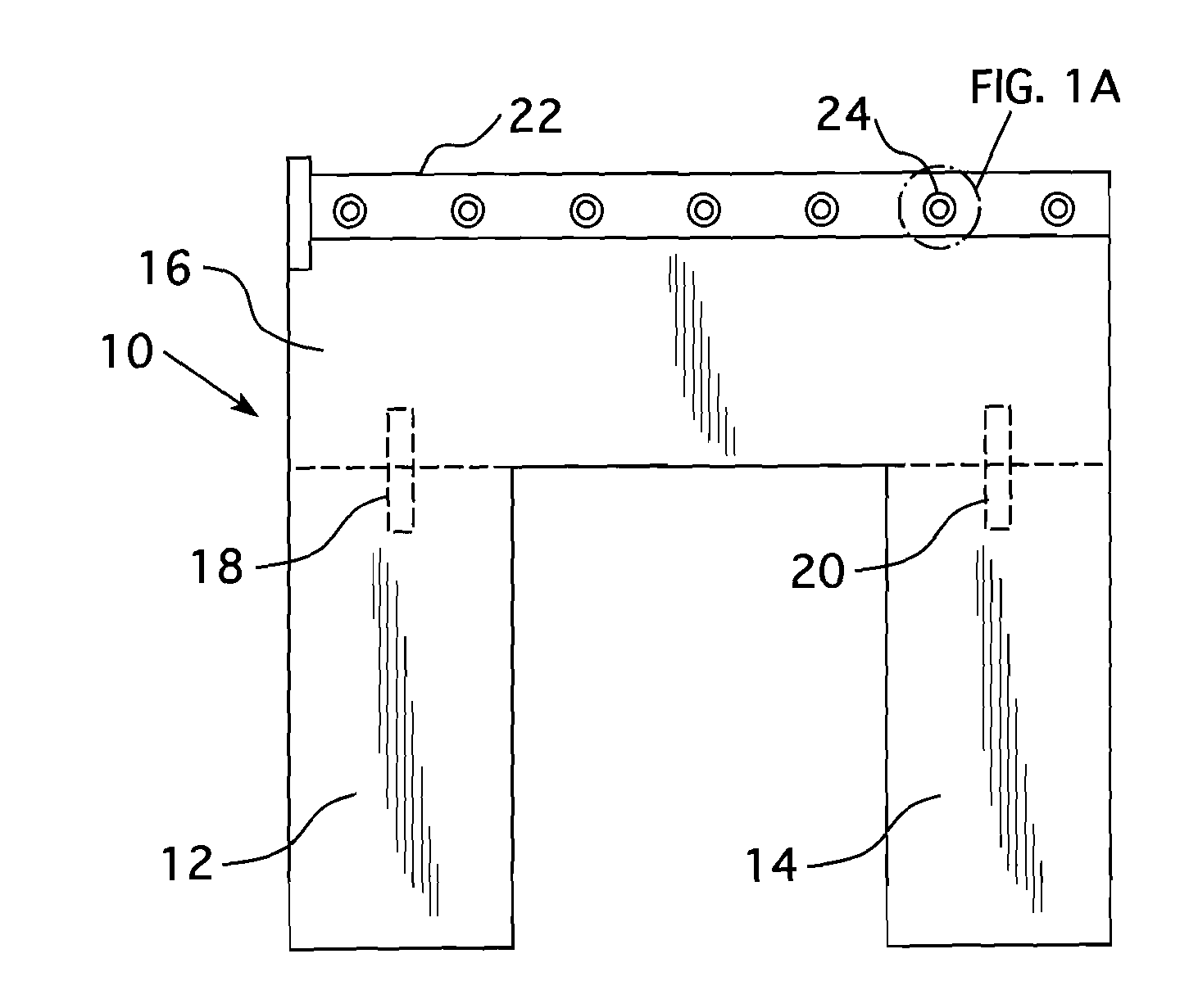
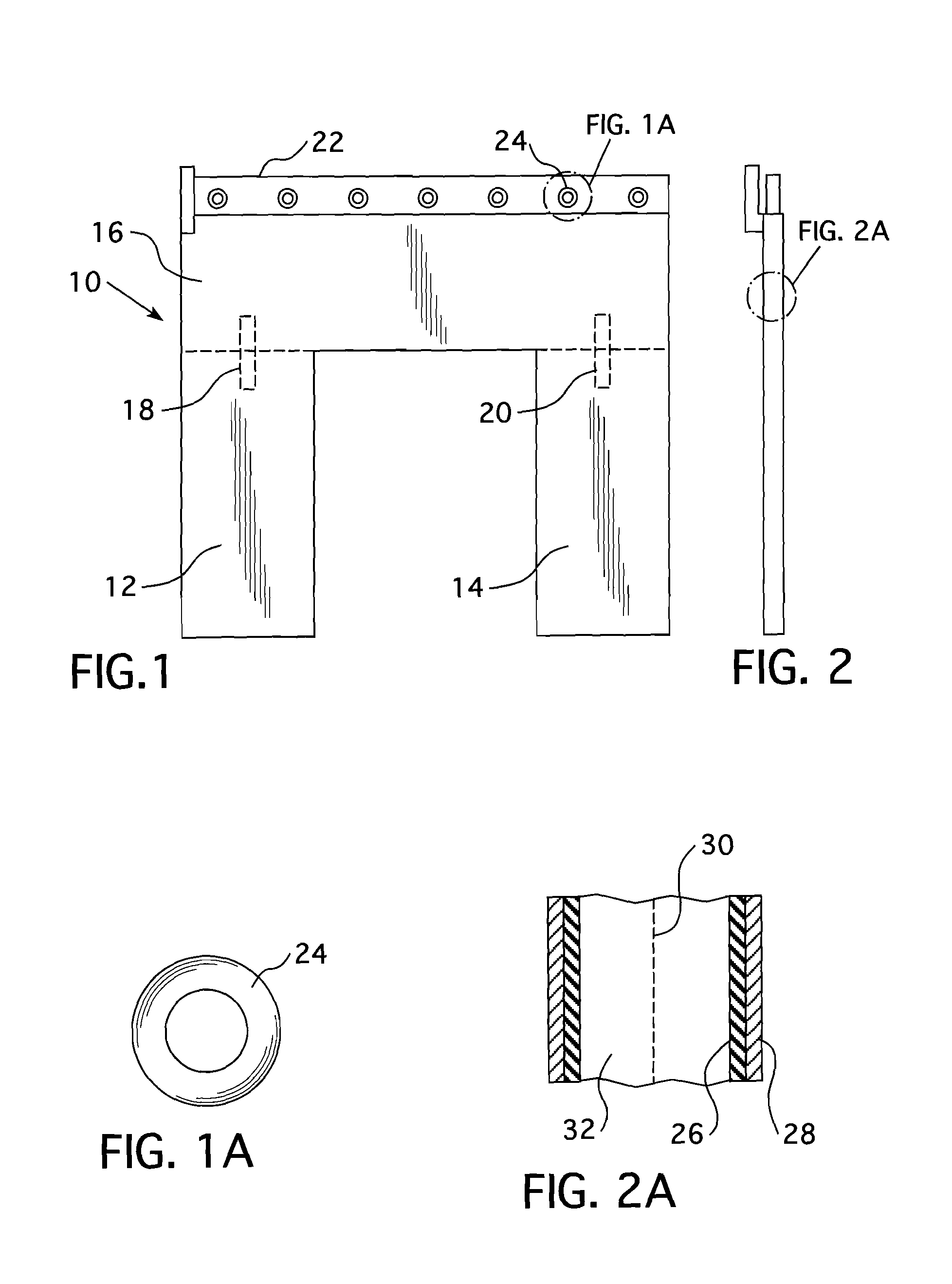
Expansion gap radiation shield
a radiation shield and expansion gap technology, applied in the field of flexible radiation shields, can solve the problems of difficult shielding by conventional methods, exacerbated problems, and highly localized radiation fields outside the gap that may not be readily detected by radiation protection personnel, and achieve the effect of reducing radiation dose rates and no loss of shielding capability
- Summary
- Abstract
- Description
- Claims
- Application Information
AI Technical Summary
Benefits of technology
Problems solved by technology
Method used
Image


Examples
Embodiment Construction
[0029]In refueling a nuclear reactor, the radioactive fuel assemblies must be removed from the reactor core and stored for an extended period of time in a spent fuel pool. In order to avoid the hazards due to radiation, the nuclear reactor core is flooded with water to a substantial depth above the top of the core with the fuel elements removed under water. Since these fuel elements are highly radioactive and still produce heat known as decay heat for a period of several months, they cannot be immediately removed from the plant but must be stored, preferably under water, which provides radiation protection and the necessary cooling.
[0030]When these spent fuel elements have sufficiently decayed, they may be removed and shipped for reprocessing, or stored at the plant in the spent fuel pool or in dry storage casks. Since the nuclear reactor will be back in operation at the time the spent fuel is removed, it is preferable that the spent fuel pool be located outside of the reactor conta...
PUM
 Abstract
Description
Claims
Application Information
 - R&D
- Intellectual Property
- Life Sciences
- Materials
- Tech Scout
- Unparalleled Data Quality
- Higher Quality Content
- 60% Fewer Hallucinations
Browse by: Latest US Patents, China's latest patents, Technical Efficacy Thesaurus, Application Domain, Technology Topic, Popular Technical Reports.
© 2025 PatSnap. All rights reserved.Legal|Privacy policy|Modern Slavery Act Transparency Statement|Sitemap|About US| Contact US: help@patsnap.com