Pen needle with quick release and/or removal system

a pen needle and quick release technology, applied in the field of pen needles with quick release and/or removal systems, can solve the problems of contact with the needle tip, nothing to prevent the reuse of the needle tip, and the risk of action, so as to prevent the re-use of the tip

Active Publication Date: 2010-11-18
STAT MEDICAL DEVICES
View PDF68 Cites 41 Cited by
  • Summary
  • Abstract
  • Description
  • Claims
  • Application Information

AI Technical Summary

Benefits of technology

[0013]The tip may further comprise a safety shield arranged on the proximal end of the body. The safety shield may be movable at least between an initial position and an extended position. The initial position and the extended position may each cover a free end of the needle. The safety shield may be movable at least between an initial position, a retracted position, and an extended position. The initial position may cover a free end of the needle and the retracted position may

Problems solved by technology

That is, there is nothing to prevent reuse of the needle tip 5 should someone attempt to reinstall the needle tip onto the end 2.
As is apparent, this action can be risky because the user can possibly inadvertently be pricked by the needle N either in attempting to properly grip the needle tip 5, in the action of rotating it to the

Method used


Image

  • Pen needle with quick release and/or removal system
  • Pen needle with quick release and/or removal system
  • Pen needle with quick release and/or removal system

Examples


Embodiment Construction

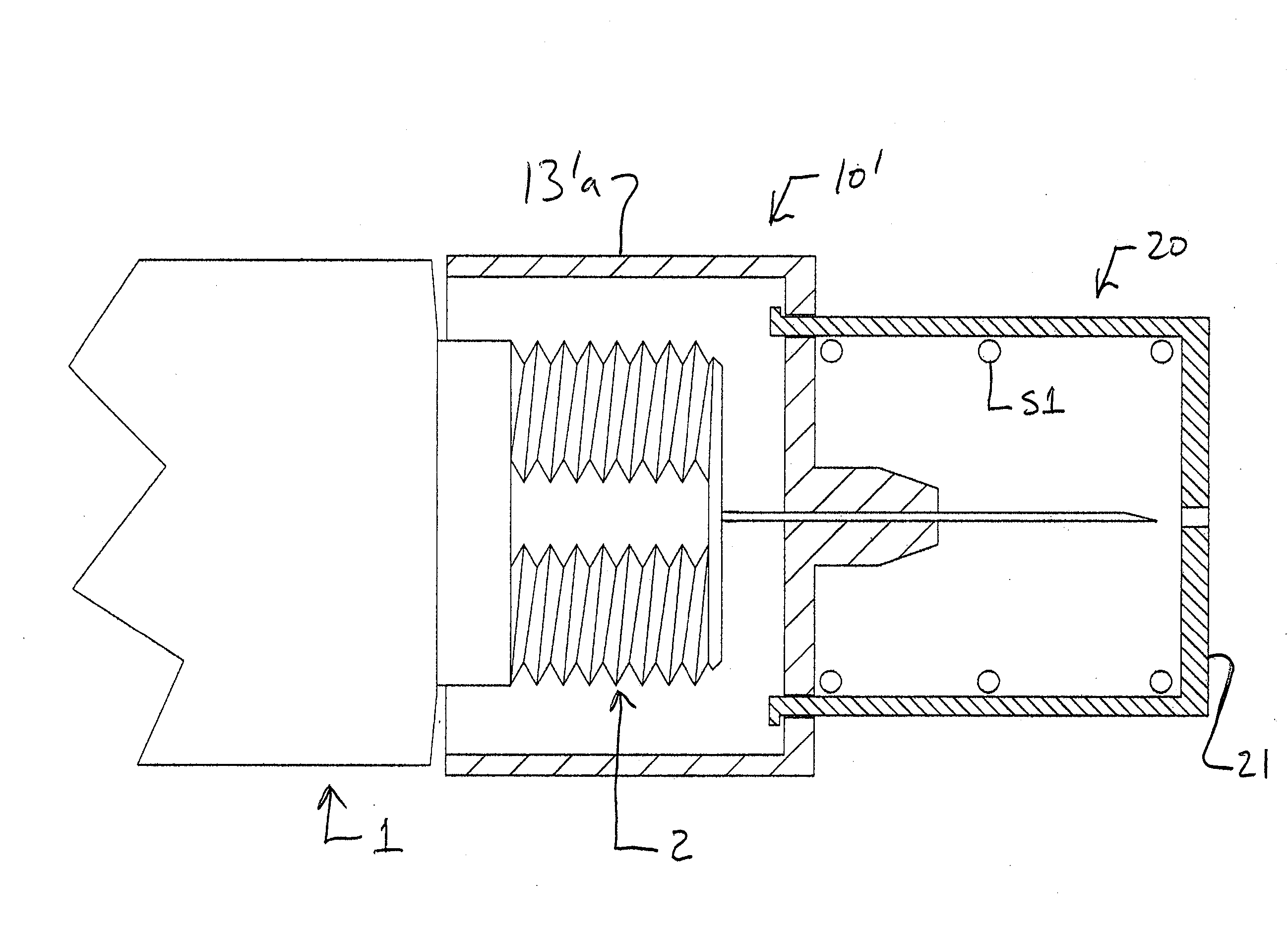
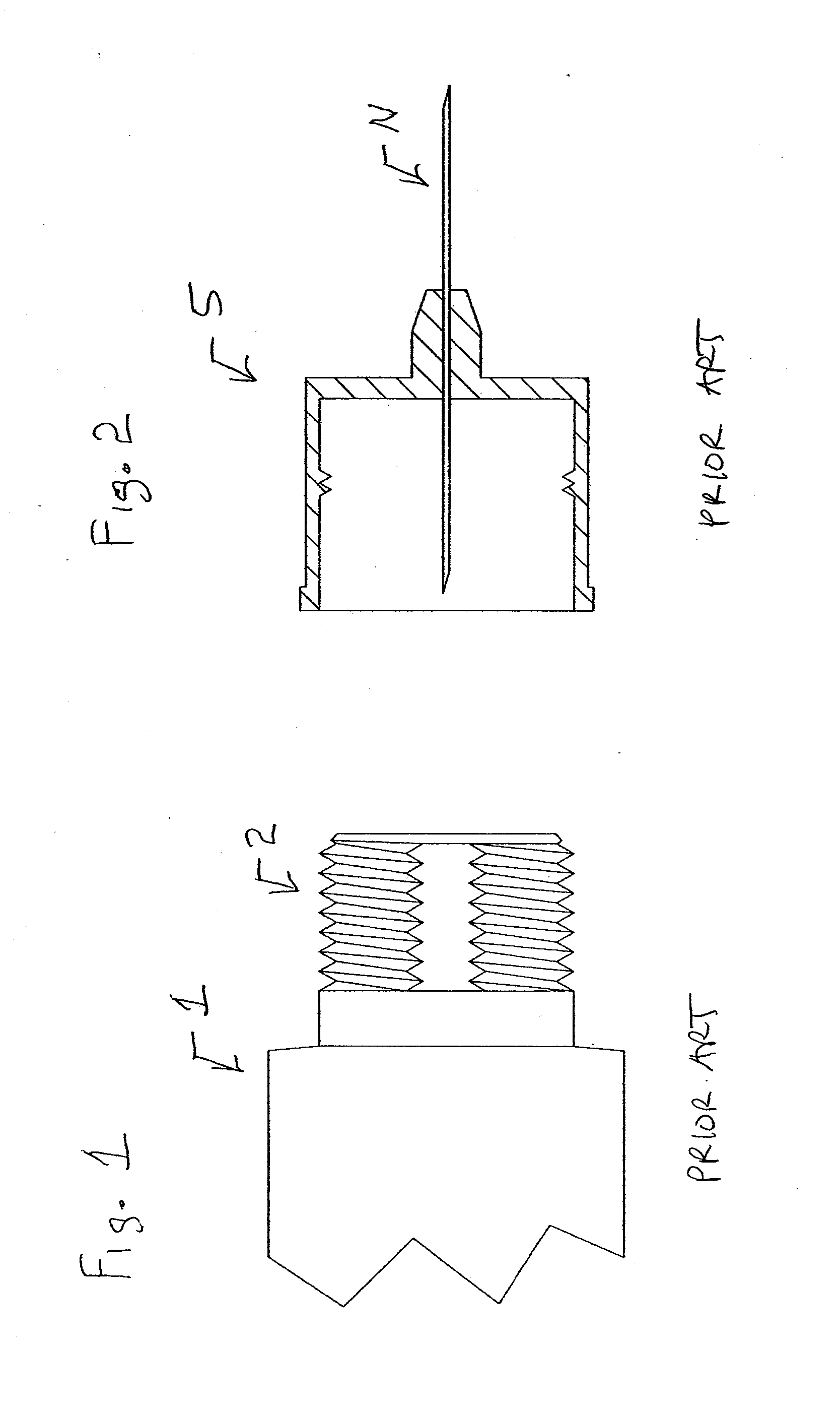
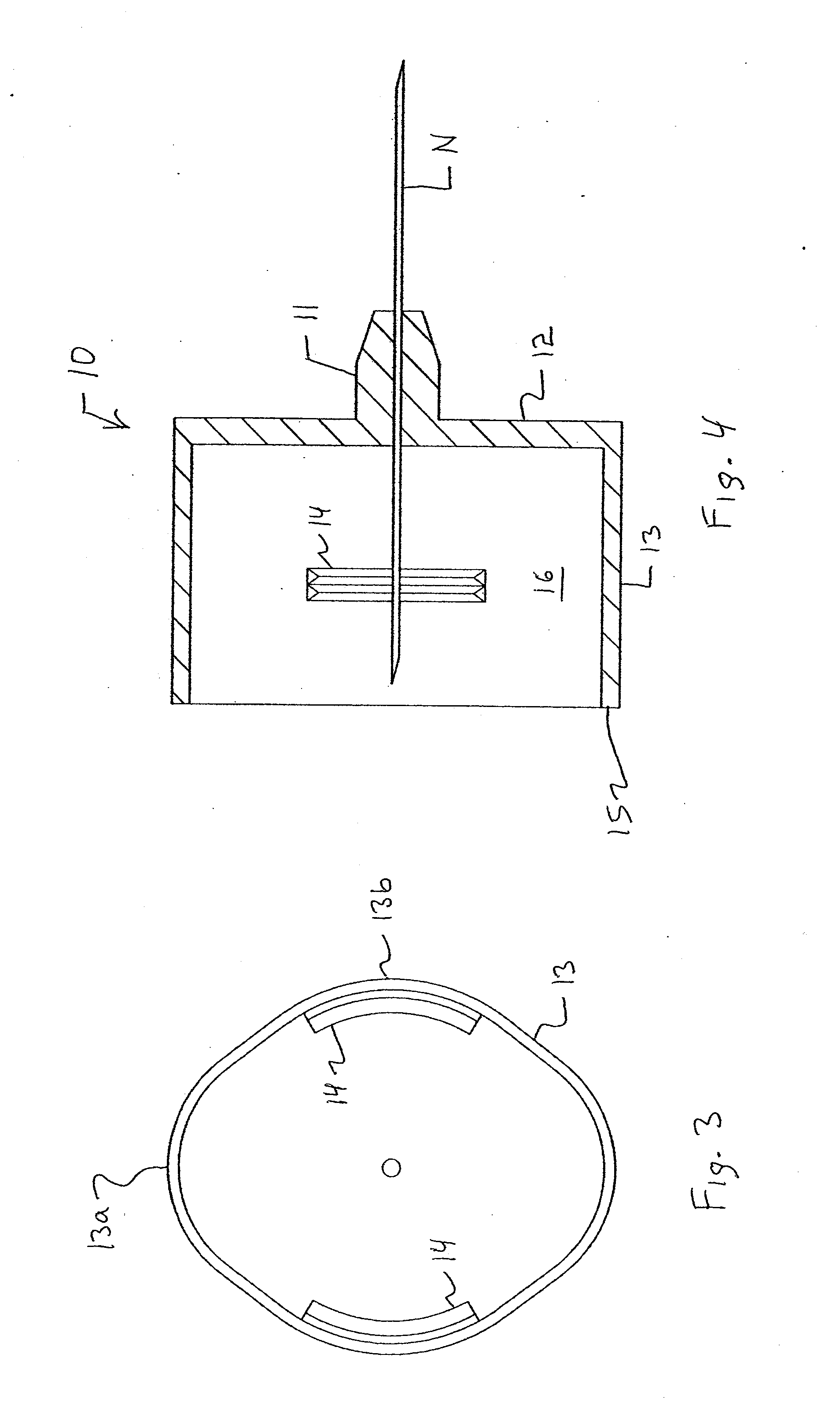
[0068]Referring now to the drawings and first to FIGS. 3-6 which shows a first embodiment of a needle tip assembly. Although not shown, the needle tip assembly includes a needle tip cap (similar to cap 30 in US 2008 / 0154192) having various generally cylindrical portions with different diameters, a needle cap (similar to cap 40 in US 2008 / 0154192), and a pen needle or tip assembly 10. The proximal end of the pen needle 10 includes a needle N while the distal end 15 includes an opening which is sized to allow the pen needle 10 to be mounted to the threaded proximal end 2 of the pen needle injection device 1. The tip 10 includes a main support 11, a proximal surface or end 12, an inner space 16, and two oppositely arranged thread sections 14. The body 13 has an generally oval shape, is made of an elastic material such as synthetic resin, and includes two oppositely arranged inwardly deformable / deflectable sections 13a and with two oppositely arranged outwardly deformable / deflectable se...


PUM


Abstract

An injection device tip includes a body configured to be removably connected to an injection device and a needle having a portion projecting from a proximal end of the body. The body at least one of has flexible portions which can be deflected inwardly to cause release of an engagement between the body and a proximal end of the injection device, has two oppositely arranged flexible portions arranged outside an imaginary circle defined by an outside surface of two opposite portions arranged between the two oppositely arranged flexible portions, is generally oval in shape, is generally rectangular in shape, is generally square in shape, and is non-circular in shape. This Abstract is not intended to define the invention disclosed in the specification, nor intended to limit the scope of the invention in any way.

Description

CROSS-REFERENCE TO RELATED APPLICATIONS[0001]The instant application is a US non-provisional Application based on U.S. provisional application No. 61 / 178,673, filed May 15, 2009, the disclosure of which is hereby expressly incorporated by reference hereto in its entirety.BACKGROUND OF THE INVENTION[0002]1. Field of the Invention[0003]This invention relates generally to pen injection devices, e.g., pre-loaded syringes, such as are utilized for injection of medicament into the body tissues of human and animal patients. More specifically, this invention relates to a removable pen needle which is more easily removed from the pen injection device. The pen needle can preferably include a safety system or shield to prevent inadvertent pricking on a user.[0004]This invention also relates to a method of using pen needles for pen injection devices wherein the pen needle is configured to be used with conventional the pen injection device.[0005]This invention also relates to a method of using p...

Claims


Application Information

Patent Timeline
IPC IPC(8): A61M5/34A61M5/32
CPCA61M5/3202A61M5/3205A61M5/326A61M5/347A61M2005/3267A61M2005/3247A61M2039/1016A61M2039/1027A61M2005/3246
Inventor SCHRAGA, STEVEN
Owner STAT MEDICAL DEVICES
Why Eureka
Try Eureka