
Projection apparatus and transparent screen for it

a technology of projection apparatus and transparent screen, which is applied in the field of projection image display apparatus, can solve the problems of large reflection loss, inability to control the brightness direction of the peak, and generate large reflection loss, etc., and achieve the effects of reducing the length of the arm, reducing the strength of the beam, and correcting aberration

Active Publication Date: 2010-11-18
MAXELL HLDG LTD
View PDF16 Cites 21 Cited by
  • Summary
  • Abstract
  • Description
  • Claims
  • Application Information

AI Technical Summary

Benefits of technology

[0011]On the other hand, JP-A-2006-259252 has proposed an idea having a mirror mechanism unit for enabling to rotate a mirror for reflecting projection light to be projected from a projection lens of a projector main body, wherein this mirror mechanism unit fixes the projector main body to a fixing unit so that a projection angle of the projection light from the projector main body attains a predetermined angle relative to the mirror, and is capable of performing projection from a rear surface relative to the screen (hereafter described as rear projection) without shifting the projection lens arranged inside the projector main body, as well as, in the case of performing front projection (direct projection onto the screen), the mirror mechanism unit has a configuration to store the projector main body in the above mirror mechanism unit, and in the case where the projector main body is stored inside the mirror mechanism, a compact size is attained.
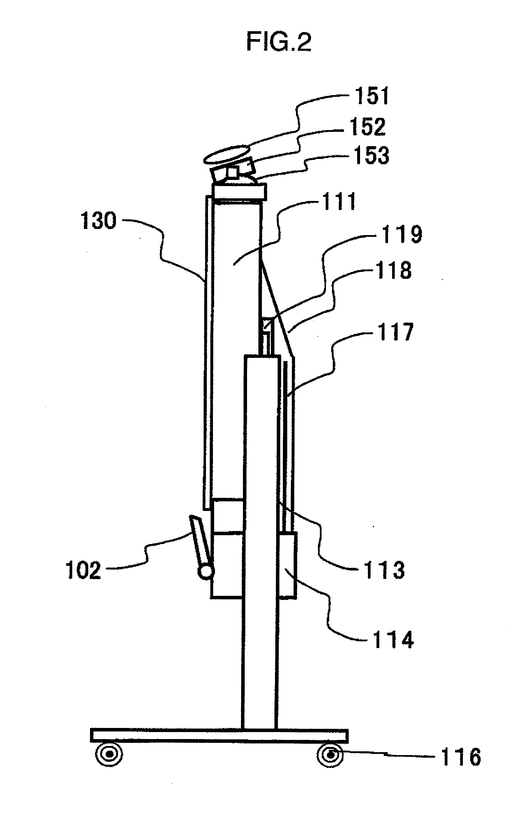
[0033]In addition, by the caster for transferring attached at the lower part of the main body or the adjustment mechanism of screen height (position), the portability and usability are enhanced. Still more by arranging the camera, and the directive microphone as a voice input unit at the upper end of the screen, it becomes possible to enhance the interactive property or the crime prevention property.

Problems solved by technology

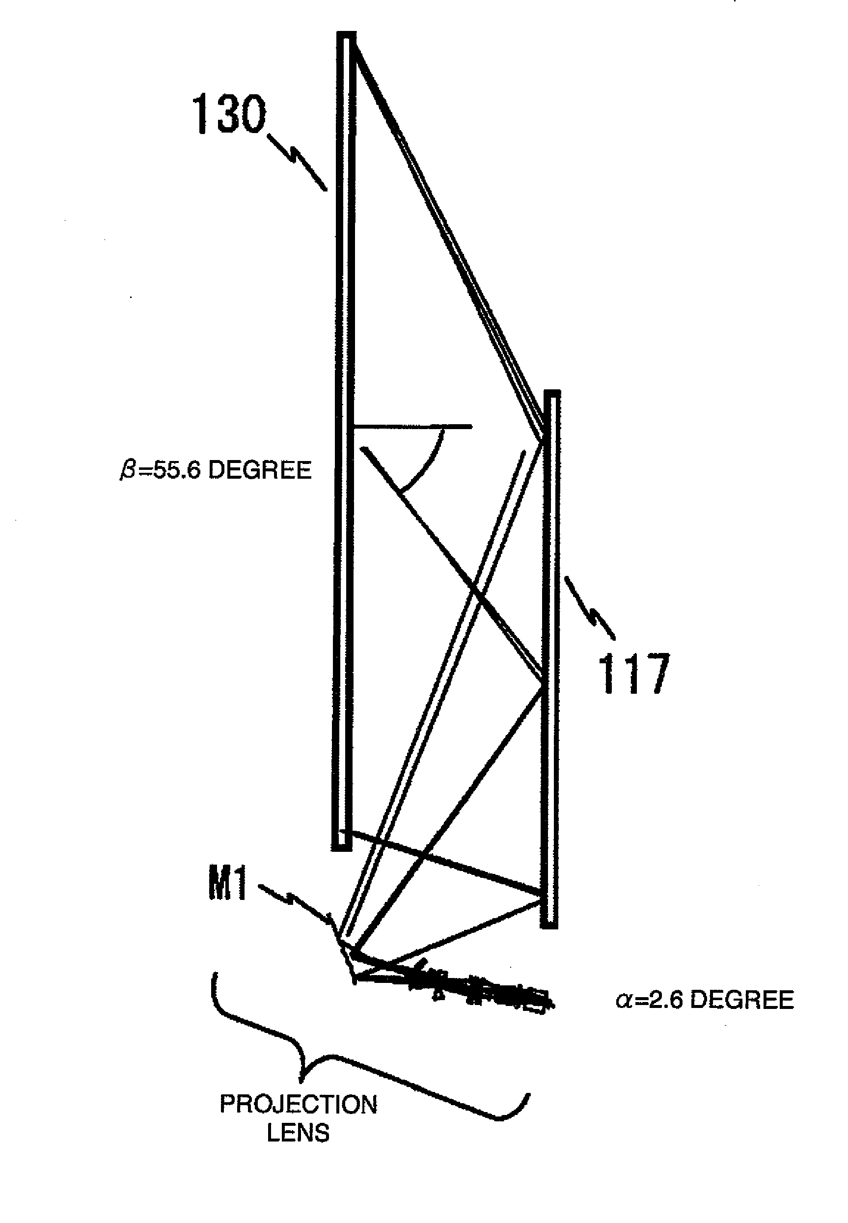
Application of this transparent screen to the oblique projection optical system, as illustrated in FIG. 38, does not provide sufficient refraction of image light R1 and R2, and the image light R1 and R2 enters onto the diffusion sheet 170 from an oblique direction, so that a peak brightness direction is not only unable to be controlled to a desired direction but also it generates large reflection loss.

Method used


Image

  • Projection apparatus and transparent screen for it
  • Projection apparatus and transparent screen for it
  • Projection apparatus and transparent screen for it

Examples


second embodiment

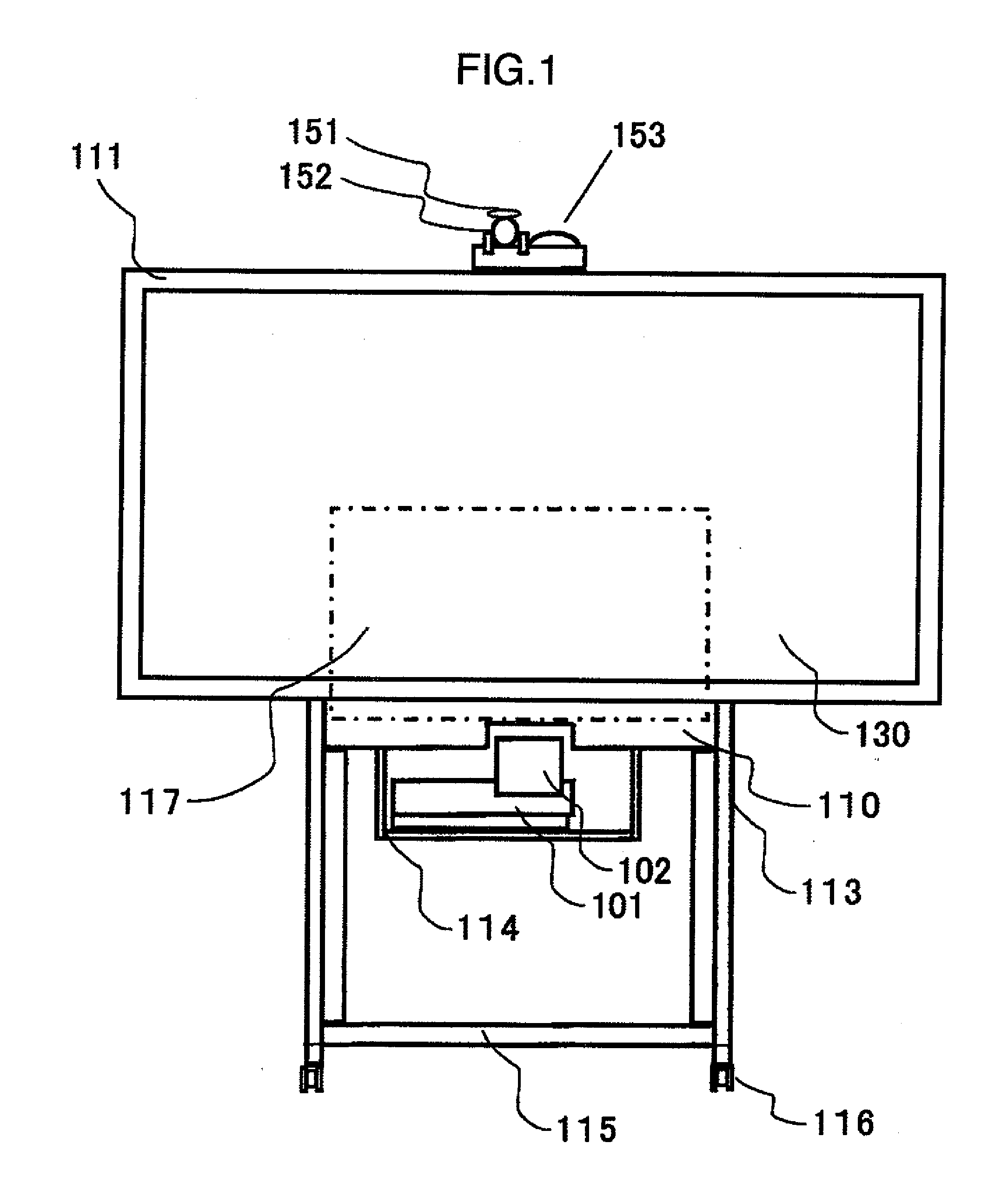
[0091]FIG. 5 is a front view of a rear-system projection apparatus according to the present invention, and a difference from FIG. 1 is that the aspect ratio of the projection surface is 4:3. Because configuring parts and action of each of the parts are common, explanation on them are omitted here.

third embodiment

[0092]FIG. 6 is a front view of a rear-system projection apparatus according to the present invention, and a different point from FIG. 1 is that the projection image display apparatus main body 101 is arranged being shifted from the center of the external shape of the transparent screen 130 of the display surface (hereafter referred to as lateral projection), Explanation will be given below on a specific technical means to attain the above arrangement in the projection lens to attain the oblique projection optical system with reference to FIG. 9. A zone A of FIG. 9 shows an effective region of an object surface of the projection lens configuring the oblique projection optical system provided in the projection apparatus according to one embodiment of the present invention. On the other hand, a zone B of the same drawing shows an effective image display region of an image display element for use in the projection image display apparatus according to one embodiment of the present inven...

fourth embodiment

[0094]FIG. 7 is a front view of a rear-system projection apparatus according to the present invention, and a different point from FIG. 1 is that two sets of the projection image display apparatus main body 101a and 101b are installed together. In addition, by installing two sets of the projection image display apparatus main bodies 101a and 101b side by side in the horizontal direction of the screen so that incident angles in the vertical direction to the transparent screen becomes the same, simultaneous projection onto two screens becomes possible. Explanation will be given below on relation among the effective region of the object surface (zone A) of the projection lens configuring the oblique projection optical system of each of the adoptable two sets of the projection image display apparatuses, and the effective image display regions, (zone B) and (zone C), of the image display element, at this time, with reference to FIG. 10.

[0095]By fixing the projection apparatus in one embod...


PUM


Abstract

There is provided a projection apparatus using an oblique projection optical system, which generates little reflection loss by providing a linear Fresnel lens at an incident surface in the case where the apparatus is used as a linear system, wherein said linear Fresnel lens makes total reflection of image light, and is capable of obtaining total surface property with good brightness in a region with small incident angle onto a screen, by using a total reflection Fresnel lens and a refraction Fresnel lens in combination. In addition, total surface property with further good brightness can be obtained by using a plurality of projection image display apparatuses in the same projection apparatus.

Description

INCORPORATION BY REFERENCE[0001]The present application claims priority from Japanese application JP-2009-115132 filed on May 12, 2009, the content of which is hereby incorporated by reference into this application.BACKGROUND OF THE INVENTION[0002]The present invention relates to a projection image display apparatus for projecting an image onto a projection surface using an image display element such as a liquid crystal panel, a screen of the projection surface, and a manufacturing method thereof, in particular, the present invention relates to technology to make a projection apparatus obtained by combination thereof more compact and higher performance.[0003]For example, in the projection image display apparatus for displaying in an enlarging way a display screen of a reflection type or transparent type liquid crystal panel, or an image display element with a structure arranged with a plurality pieces of micro mirrors, onto a screen or a board etc. of the projection surface, it is n...

Claims


Application Information

Patent Timeline
IPC IPC(8): G03B21/14G03B21/62G02B3/08G02B13/16G02B13/18G02B17/08G03B21/00G03B21/625
CPCG02B13/18G03B21/62H04N7/142G03B21/14G03B21/10
Inventor HIRATA, KOJIYATSU, MASAHIKOIKEDA, HIDEHIRO
Owner MAXELL HLDG LTD
Learn More