
Electronic ophthalmoscope for selective retinal photodisruption of the photoreceptor mosaic

Inactive Publication Date: 2010-11-18
VAN DE VELDE FRANS J
View PDF3 Cites 45 Cited by
  • Summary
  • Abstract
  • Description
  • Claims
  • Application Information

AI Technical Summary

Benefits of technology

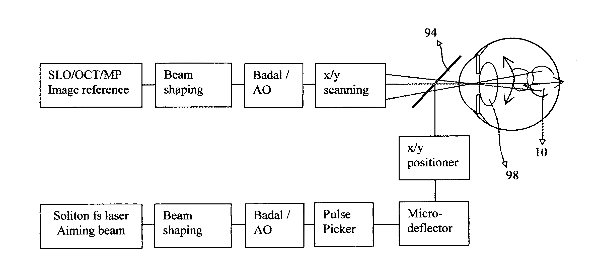
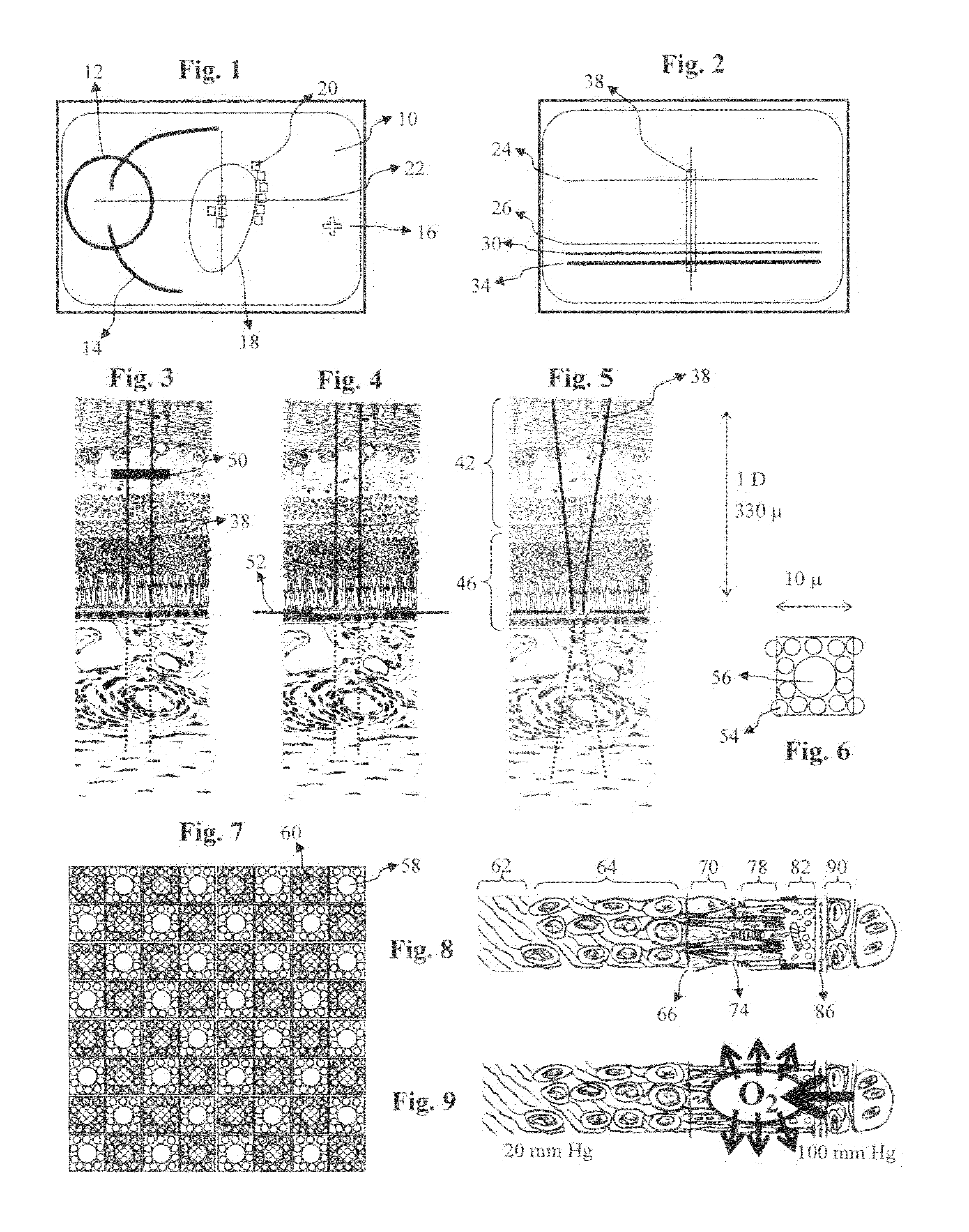
[0015]It is the principle object of this invention to disclose additional embodiments and optical configurations of the electronic ophthalmoscope. They incorporate the use of short-pulse lasers, specifically in the femtosecond domain, to selectively photodisrupt in a predetermined pattern the photoreceptor mosaic layer of the retina or Bruch's membrane.
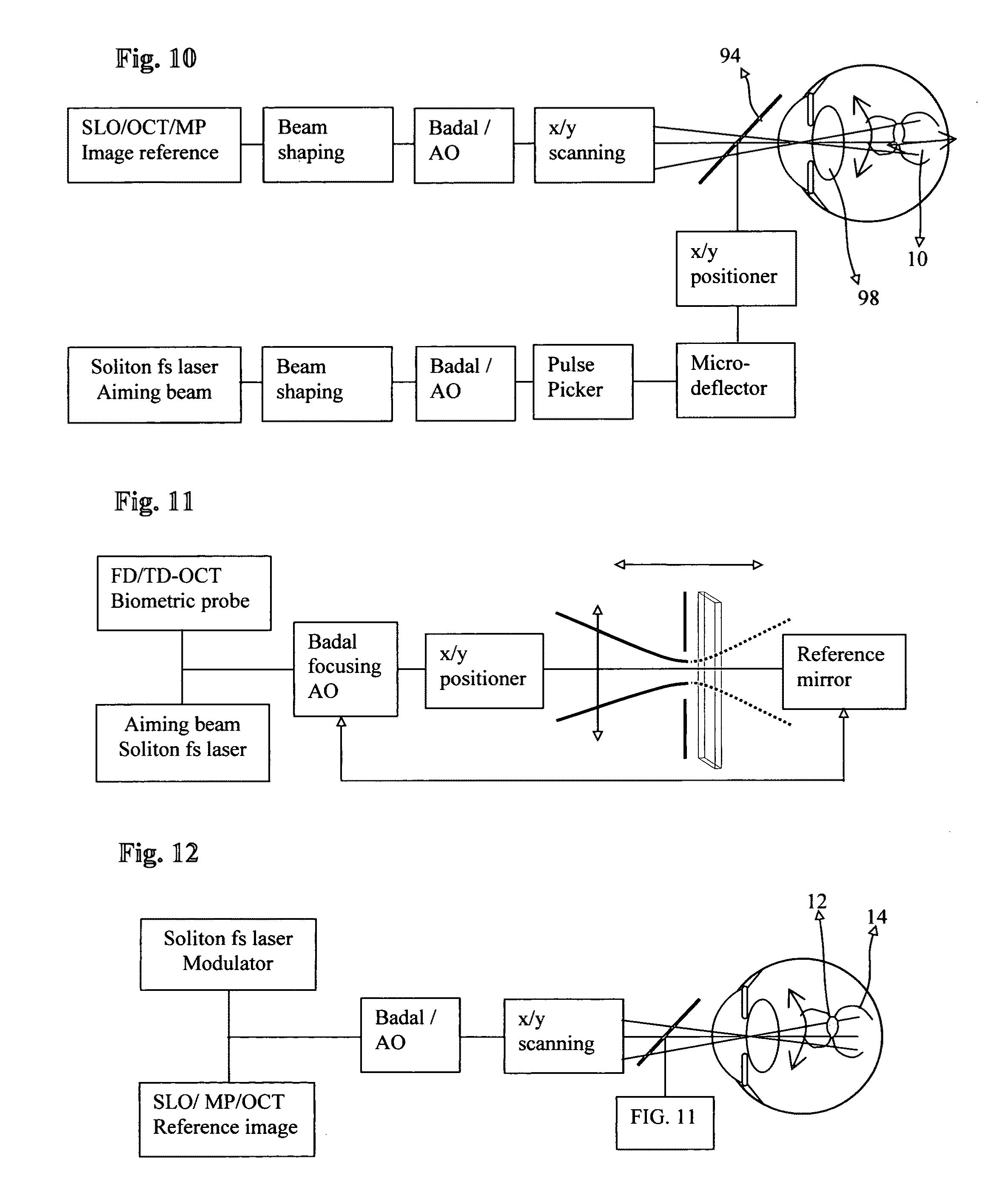
[0016]An imaging or biometric OCT channel will be of help to focus the therapeutic beam onto the targeted layer, and also to assess morphologically the effect of the treatment.
[0017]MP will be of use to assess the need for treatment in particular areas of the retina, and also to evaluate the results of such tre

Problems solved by technology

The delivery of sufficient energy to the photoreceptor layer (PR) in a confined manner and sparing

Method used


Image

  • Electronic ophthalmoscope for selective retinal photodisruption of the photoreceptor mosaic
  • Electronic ophthalmoscope for selective retinal photodisruption of the photoreceptor mosaic
  • Electronic ophthalmoscope for selective retinal photodisruption of the photoreceptor mosaic

Examples


Embodiment Construction

[0093]Representative embodiments of the electronic ophthalmoscope have been described in U.S. Pat. Nos. 7,374,287 and 7,703,922. The art of combining such instrument with various therapeutic light sources of different pulse duration has been described in U.S. Pat. Nos. 5,892,569, 5,923,399, 5,943,117, 6,186,628 and 6,789,900.

[0094]The principles and applications of scanning laser ophthalmoscopy, optical coherence tomography and microperimetry are also described in detail in the publications referenced before. Below we describe the operational environment of an ophthalmoscope that is capable of selectively disrupting in a controlled manner a pre-defined part of the photoreceptor mosaic of the retina or Bruch's membrane.

I. Anatomical and Physiological Considerations

[0095]The photoreceptor-RPE complex is by far the most active metabolic tissue in the human body, and even more so in the macular area. A huge volume of oxygen is needed to drive the Wald's visual cycle and to maintain the...


PUM


Abstract

An electronic ophthalmoscope combining scanning laser (SLO) and optical coherence (OCT) technologies is further equipped with a pulsed laser source in the femtosecond (fs) range. The goal is primarily to selectively disrupt the photoreceptor mosaic of the retina or Bruch's membrane in a pattern that minimizes loss of visual functioning, and to reduce thereby the metabolic load of the outer retina. Using a beam splitter, one embodiment combines the SLO scanning beams with the therapeutic laser beam and aiming beam. The therapeutic channel uses an independent x/y positioner and micro-deflector. Because the duty cycle is appropriate, a second embodiment can use the SLO scanners to also scan a modulated therapeutic laser beam. A biometric OCT probe, helpful in focusing, can be integrated in both configurations. A method is also disclosed to represent the tilting of the retina at a specified location.

Description

CROSS REFERENCE TO RELATED APPLICATIONS [0001]This application is related to U.S. Pat. No. 6,789,900, and U.S. Pat. Nos. 7,374,287 and 7,703,922.DESCRIPTION Background [0002]1. Field of Invention[0003]The invention relates generally to instruments for examining and treating the eye, and specifically to a version of the electronic ophthalmoscope combining SLO (scanning laser ophthalmoscopy) and OCT (optical coherence tomography) designs, and further equipped with an ultra fast pulsed laser source for administering selective retinal photodisruption laser therapy to the photoreceptor mosaic layer of the retina.[0004]2. Description of Prior Art[0005]The ophthalmoscope is well known as an important device for examining the eye, and in particular the retina. As a result of great interest in preserving eyesight, ophthalmoscopes of various constructions have been built. An electronic version of the ophthalmoscope, as described in U.S. Pat. Nos. 7,374,287 and 7,703,922, combining optimally s...

Claims


Application Information

Patent Timeline
IPC IPC(8): A61B3/12
CPCA61B3/102A61B3/1025G01B9/0203A61F9/008G01B9/02014A61B3/0008A61B3/0075G01B9/02091
Inventor VAN DE VELDE, FRANS J.
Owner VAN DE VELDE FRANS J
Learn More