
Expandable intervertebral implant and associated method of manufacturing the same

a technology of intervertebral implants and expandable implants, which is applied in the direction of prosthesis, osteosynthesis devices, impression caps, etc., can solve the problems of loss of vertebral height, fracture of vertebral discs, facet and nerve impingement, etc., and achieves the effect of reducing lung function, reducing the height of vertebrae, and reducing the size of vertebra

Active Publication Date: 2010-11-11
DEPUY SYNTHES PROD INC
View PDF5 Cites 344 Cited by
  • Summary
  • Abstract
  • Description
  • Claims
  • Application Information

AI Technical Summary

Benefits of technology

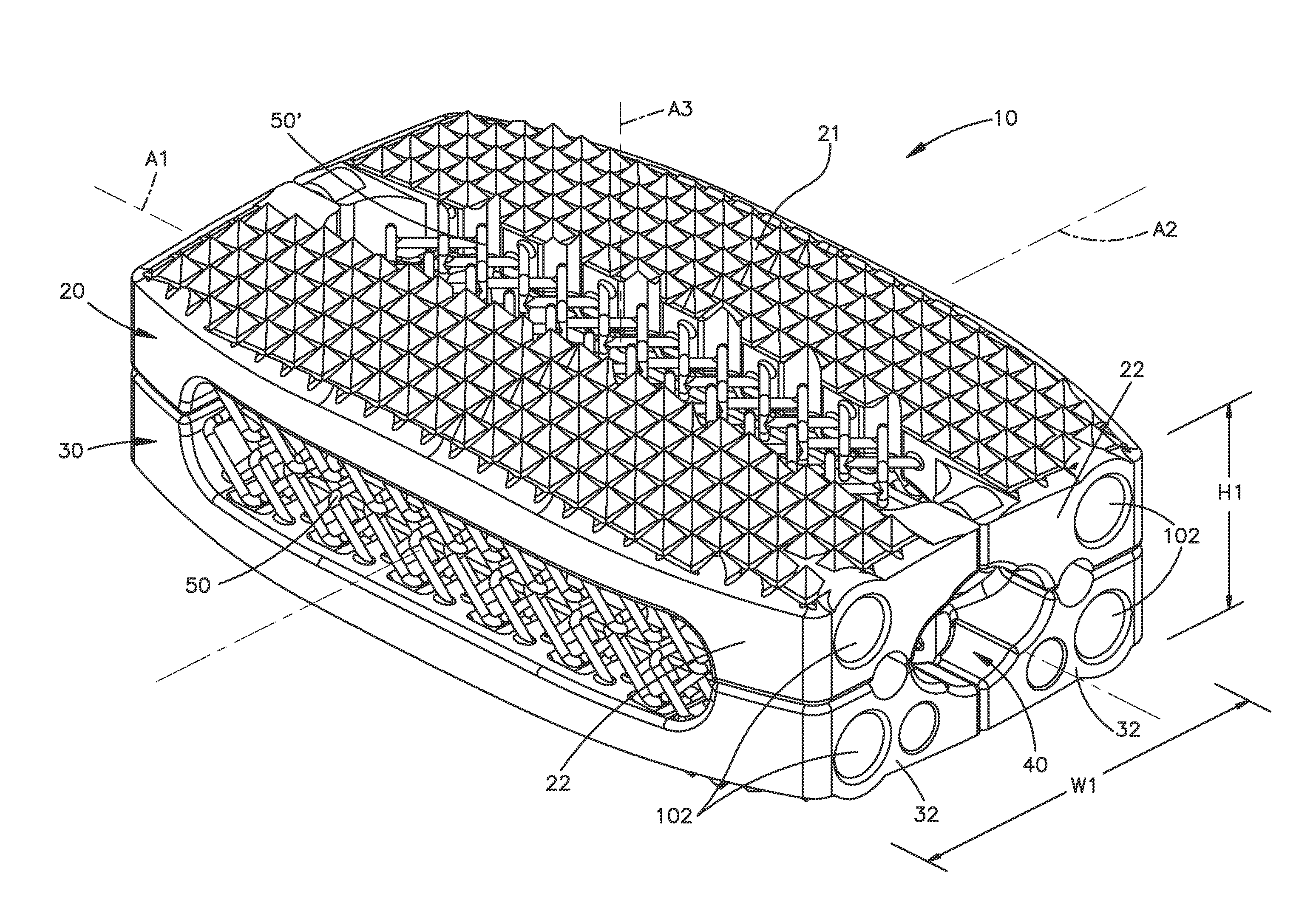
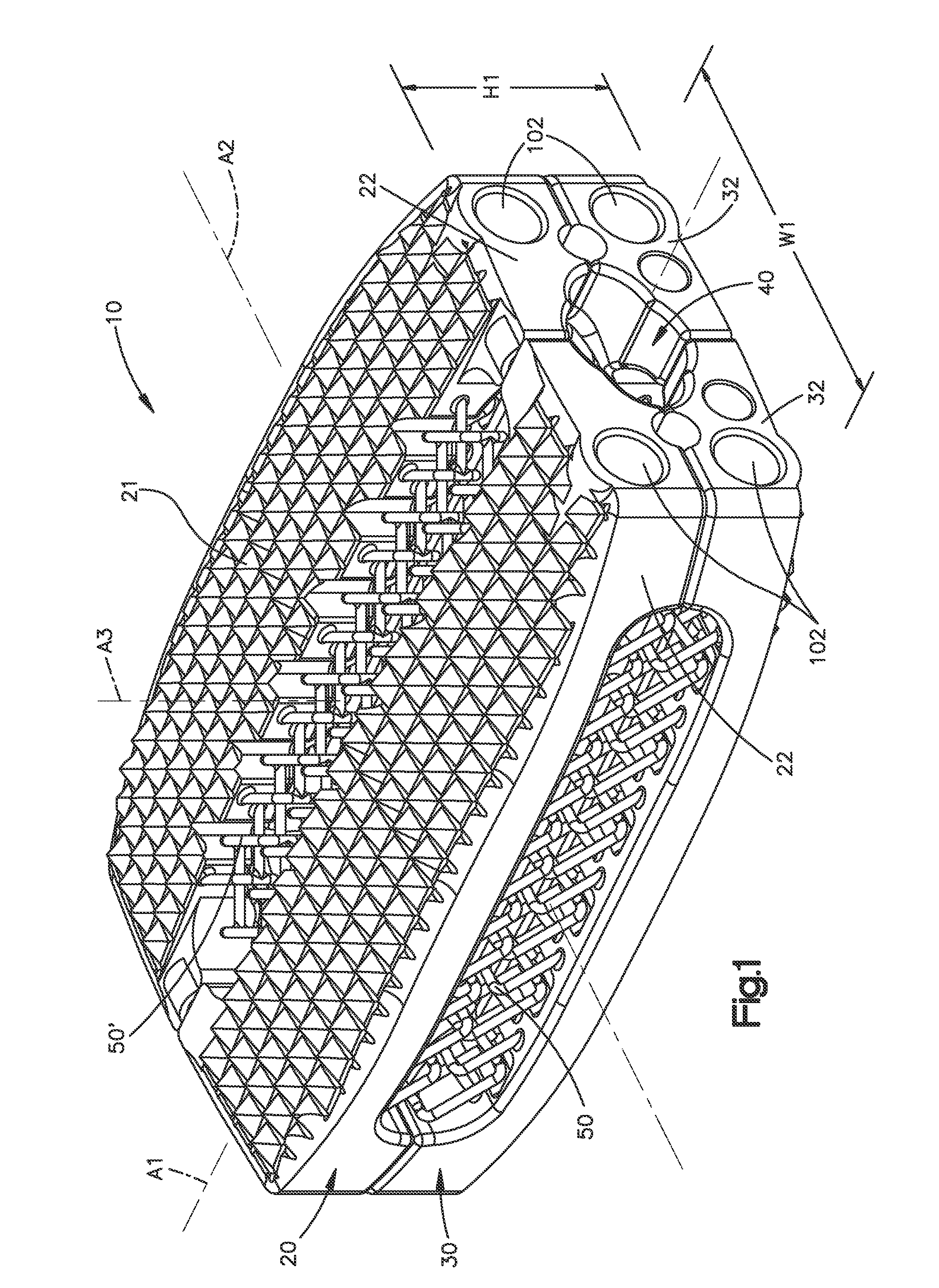
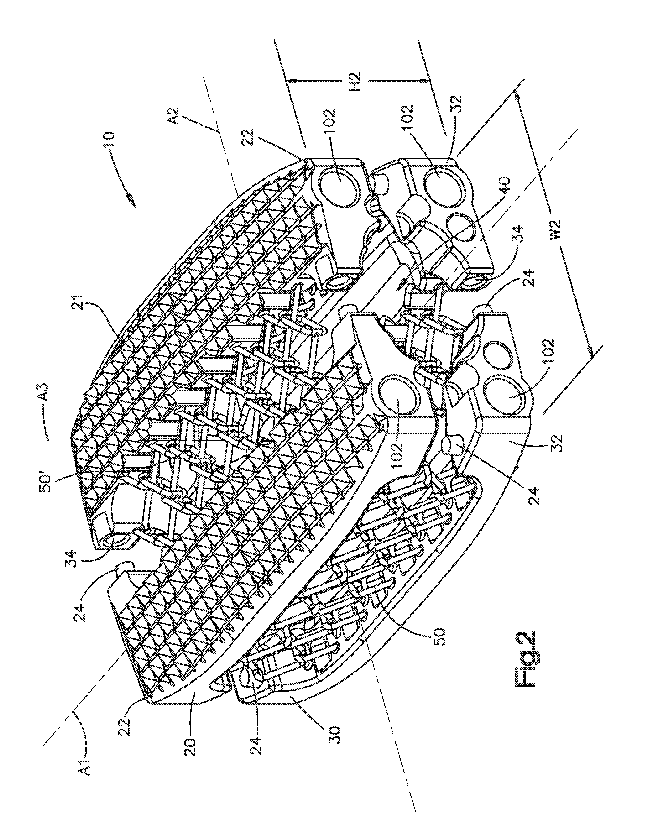
[0007]The present invention relates to an expandable intervertebral implant. More particularly, a preferred embodiment of the present invention relates to an intervertebral implant that is laterally and vertically expandable in situ from a collapsed, non-expanded or first insertion configuration to a second expanded configuration. The expandable intervertebral implant preferably includes superior and inferior bone contacting members connected together via one or more expandable components such as, for...

Problems solved by technology

One aspect of osteoporosis may be the partial or complete collapse of the bony structure of the spine, which in turn can cause loss of vertebral height, fracture of a vertebral disc, facet and nerve impingement, etc.
Collapse of the spine often results in, for example, pain, reduction of lung function, unbalanced stature, etc.
Osteoporotic bone is usually brittle, thus increasing the risk of breaking a vertebral endplate during a surgery or implantation of an implant and the endplates may have a uneven surface.
For example, a stiff implant may impact a point or small area of an uneven surface of the osteoporotic bone, thereby creating a stress concentration and potentially damaging the bone.
Another reason for not incorporating an intervertebral implant may be that the insertion approach for implanting an intervertebral implant is difficult and risky, especially in elderly patients.

Method used


Image

  • Expandable intervertebral implant and associated method of manufacturing the same
  • Expandable intervertebral implant and associated method of manufacturing the same
  • Expandable intervertebral implant and associated method of manufacturing the same

Examples


Embodiment Construction

[0027]Certain terminology is used in the following description for convenience only and is not limiting. The words “right”, “left”, “top” and “bottom” designate directions in the drawings to which reference is made. The words “inwardly” and “outwardly” refer to directions toward and away from, respectively, the geometric center of the device and designated parts thereof. The words, “anterior”, “posterior”, “superior”, “inferior”, “lateral” and related words and / or phrases designate preferred positions and orientations in the human body to which reference is made and are not meant to be limiting. The terminology includes the above-listed words, derivatives thereof and words of similar import.

[0028]Certain exemplary embodiments of the invention will now be described with reference to the drawings. In general preferred embodiments of the present invention are directed to (i) an expandable intervertebral implant 10 for implantation between or to replace damaged portions of adjacent vert...


PUM

PropertyMeasurementUnit
Shapeaaaaaaaaaa
Widthaaaaaaaaaa
Heightaaaaaaaaaa

Abstract

An expandable intervertebral implant (10) includes superior (20) and inferior (30) bone contacting members and at least one vertical wire netting (50) interconnecting the superior and inferior bone contacting members. The superior and inferior bone contacting members include at least two bone contacting components interconnected via one or more lateral wire nettings such that the implant is vertically and laterally expandable in situ from a first insertion configuration to a second expanded configuration. The vertical and lateral wire netting are preferably constructed of a plurality of individual link members. The present invention also preferably relates to an associated method of manufacturing the intervertebral implant such that the intervertebral implant can be manufactured as an integral component or part.

Description

CROSS-REFERENCE TO RELATED APPLICATIONS[0001]This application claims the benefit of U.S. Provisional Application No. 61 / 021,778, filed on Jan. 17, 2008, entitled “INTERVERTEBRAL SPACE AUGMENTATION,” the contents of which is incorporated in its entirety by reference herein.BACKGROUND OF THE INVENTION[0002]People, especially elderly people, may suffer from osteoporosis. One aspect of osteoporosis may be the partial or complete collapse of the bony structure of the spine, which in turn can cause loss of vertebral height, fracture of a vertebral disc, facet and nerve impingement, etc. Collapse of the spine often results in, for example, pain, reduction of lung function, unbalanced stature, etc. One treatment option may be a surgical procedure to re-align the vertebra (e.g., to re-establish balanced curvature of the spine as well as the intervertebral disc space).[0003]Re-alignment of a spine including a damaged vertebra or disc may be accomplished by replacing the damaged vertebra, disc...

Claims


Application Information

Patent Timeline
IPC IPC(8): A61F2/44B05D3/00B05D3/06
CPCA61F2/3094A61F2/44A61F2/442A61F2250/0009A61F2002/30556A61F2002/30579A61F2002/3055B33Y80/00A61F2220/0016B33Y10/00Y02P10/25B22F10/34B22F10/28B22F12/41A61B17/70A61L27/04A61F2250/009A61F2002/30593A61F2/4425A61F2/4455A61F2002/4495A61F2/30771A61F2002/30462A61F2002/30518A61F2002/30785A61F2002/30843A61F2002/30904
Inventor LECHMANN, BEATBURKARD, DOMINIQUEFIERLBECK, JOHANNNIEDERBERGER, ALFRED
Owner DEPUY SYNTHES PROD INC
Learn More