
Method of detecting anomalies in a communication system using symbolic packet features

a communication system and feature detection technology, applied in the field of anomaly detection on packet switched communication systems, can solve the problems of insatiable known solutions, computational complexity and memory requirements, and the inability to describe the normal traffic in the communication network by stable, and achieve the reduction of computational complexity and memory requirements, and the effect of increasing reliability

Active Publication Date: 2010-11-11
TELECOM ITALIA SPA
View PDF9 Cites 105 Cited by
  • Summary
  • Abstract
  • Description
  • Claims
  • Application Information

AI Technical Summary

Benefits of technology

[0021]The Applicant has noticed that there is a need in the field for achieving an anomaly detection method providing increased reliability and, preferably, reduced computational complexity and memory requirements. In accordance with a particular embodiment, the Applicant has observed that advantages can be obtained by monitoring the statistical behavior of symbolic packet features associated with two packet flow portions lying in corresponding time windows that are moving in time.

Problems solved by technology

The Applicant has observed that the known solutions are not satisfactory with respect to the achieved false-negative and false-positive rates and the computational complexity and memory requirements.
This could be due to the fact that it is difficult for the normal traffic in communications networks to be described by stable probability distributions.
Moreover, it is difficult to define statistical models of communication systems that would give rise to sufficiently low false-positive and false-negative rates.
It should be also noticed that the complexity of the proposed statistical methods may be unacceptably high for high-speed and high-volume communications networks.

Method used


Image

  • Method of detecting anomalies in a communication system using symbolic packet features
  • Method of detecting anomalies in a communication system using symbolic packet features
  • Method of detecting anomalies in a communication system using symbolic packet features

Examples


first embodiment

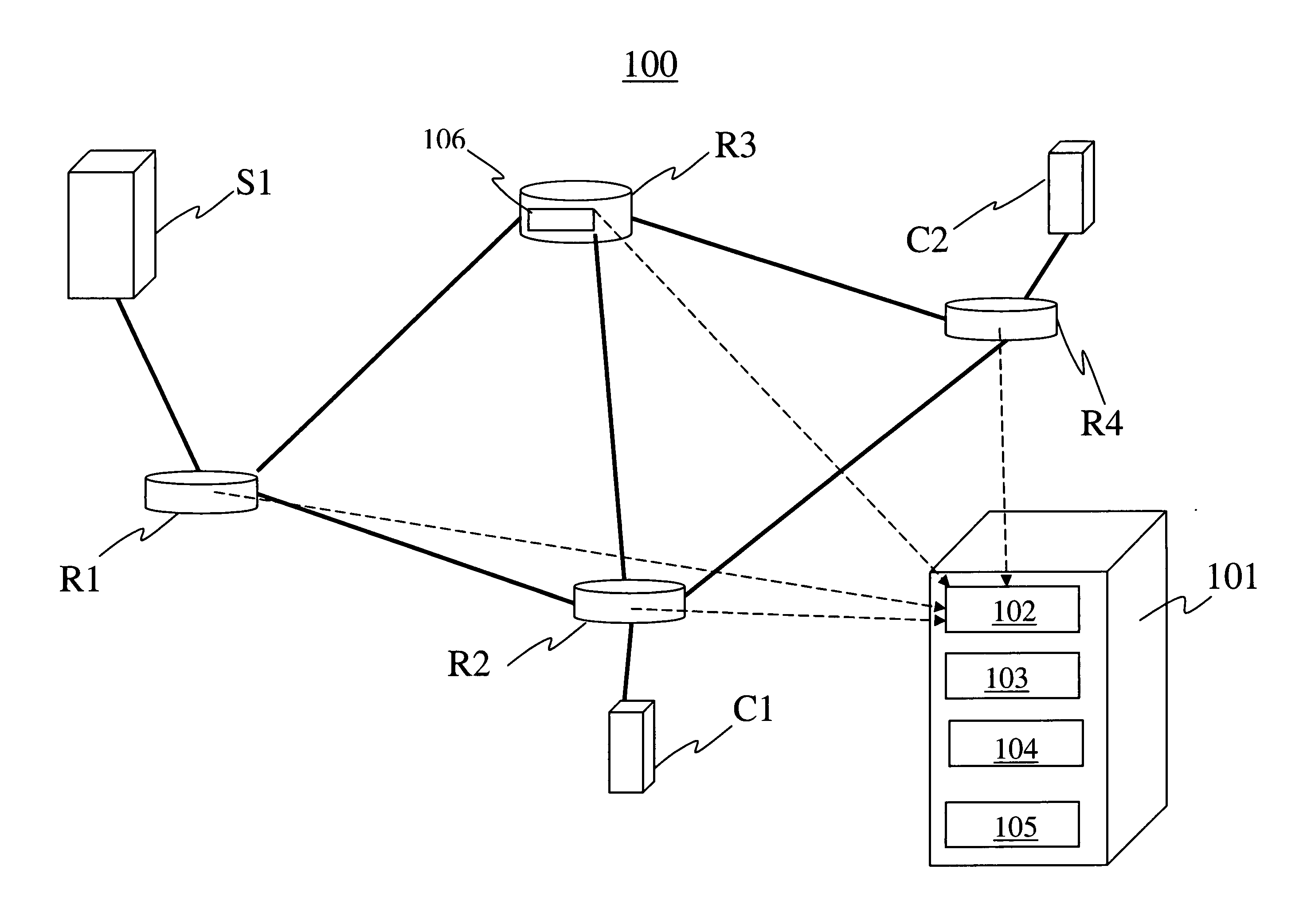
[0064]A first embodiment 300 of the detection method 200, is described herein below with reference to FIG. 3. Symbolic feature x is one of the above identified symbolic features extracted from flows of network packets, at a chosen network node, in (elementary) short time intervals of length ΔT, in some time units (e.g., ΔT is comprised 1 s−5 min), where ΔT can vary in time. In particular, as indicated above x can be the packet rate Rpacket, the average packet size Nsize, or the byte rate Rbyte suitably grouped, quantized, or hashed into a smaller set of symbolic values. For Rpacket and Rbyte, the zero values are allowed, if there are no packets with chosen features in the considered short time interval, whereas Nsize has to be positive and is not defined if in the considered short time interval there are no packets with chosen features. If the features relate to individual network packets, then ΔT corresponds to the packet inter-arrival time. The corresponding sequence of samples of...

second embodiment

[0096]According to a second example of the detection method 200, the two successive windows are defined in a different way with respect to the first embodiment.

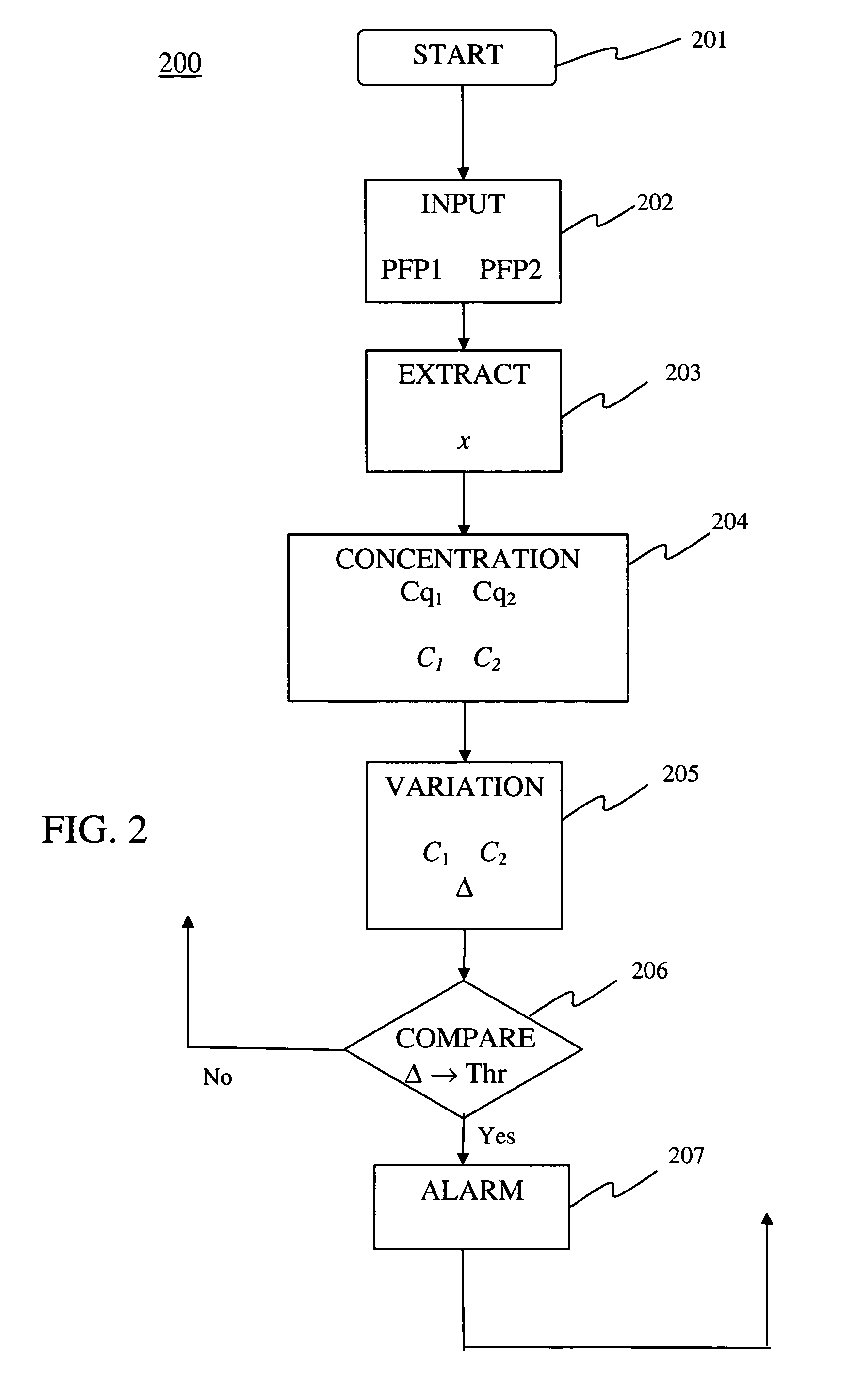
[0097]According to this second embodiment, in step 202 at time j+1, the following first and second sample segments corresponding to packet flow portions PFP1 and PFP2, respectively, are considered:

(xi)i=mj+1−nj+1mj  (22)

(xi)i=mj+1−nj+1mj+1  (23)

where the first segment (22) is the initial part of the second segment, without the ending part (xi)i=mj+1mj+1 or, equivalently, the last part of the preceding segment (xi)i=mj+1−nj+1mj+1, without the initial part (xi)i=mj−nj+1mj+1−nj+1.

[0098]FIG. 6 shows schematically two successive sliding windows W1 and W2, as in FIG. 4, with a difference that the first packet flow portion PFP1 is now associated with a shortened window W1′, extending from τ to T, whereas the second packet flow portion PFP2 is associated with W2 as in FIG. 4. In this way, the past data leaving the current sliding win...

third embodiment

[0101]In a third embodiment of the detection method 200, a moving window of increasing length is defined. Such moving window extends from a chosen initial time up to the current time, and each time, the ending point of the moving window advances τ units of time, where τ determines the resolution in time for detecting the anomalous changes in traffic. FIG. 7 shows schematically three exemplary successive windows Wj+1, and Wj+2 drawn in accordance with this third embodiment of the detection method 200. In FIG. 7, t denotes a generic time.

[0102]At each time, the packet flow portions PFP1 and PFP2 correspond to two successive moving windows. Accordingly, for a generic window index j, the packet flow portion PFP1 is defined by the segment

(xi)i=1mj  (24)

which is associated with the jth moving window containing mj samples, and the packet flow portion PFP2 is defined by the segment

(xi)i=1mj+1  (25)

which is associated with the (j+1)th moving window containing mj+1 samples.

[0103]According to ...


PUM


Abstract

A method of detecting anomalies in a communication system includes: providing a first packet flow portion and a second packet flow portion; extracting samples of a symbolic packet feature associated with a traffic status of the first and second packet flow portions; computing from the extracted samples a first statistical concentration quantity and a second statistical concentration quantity of the symbolic feature associated with the first and second packet flow portions, respectively; computing from the concentration quantities a variation quantity representing a concentration change from the first packet flow portion to the second packet flow portion; comparing the variation quantity with a comparison value; and detecting an anomaly in the system in response to the comparison.

Description

BACKGROUND[0001]1. Technical Field[0002]The present invention relates to anomaly detection on packet switched communication systems. Particularly, the present invention is related to statistical methods for detecting network traffic anomalies due to network attacks or to communication system failures.[0003]2. Description of the Related Art[0004]Several types of attacks are known, such as: (distributed) denial of service ((D)DoS) attacks, scanning attacks, SPAM or SPIT attacks, and malicious software attacks.[0005]Denial-of-Service (DoS) attacks and, in particular, distributed DoS (DDoS) attacks are commonly regarded as a major threat to the Internet. A DoS attack is an attack on a computer system or network that causes a loss of service or network connectivity to legitimate users, that is, unavailability of services. Most common DoS attacks aim at exhausting the computational resources, such as connection bandwidth, memory space, or CPU time, for example, by flooding a target networ...

Claims


Application Information

Patent Timeline
IPC IPC(8): H04L12/26
CPCH04L43/022H04L2463/141H04L63/1458H04L63/1425
Inventor GOLIC, JOVAN
Owner TELECOM ITALIA SPA
Learn More