Pwm controller and control method for a dc-dc voltage converter
- Summary
- Abstract
- Description
- Claims
- Application Information
AI Technical Summary
Benefits of technology
Problems solved by technology
Method used
Image
Examples
second embodiment
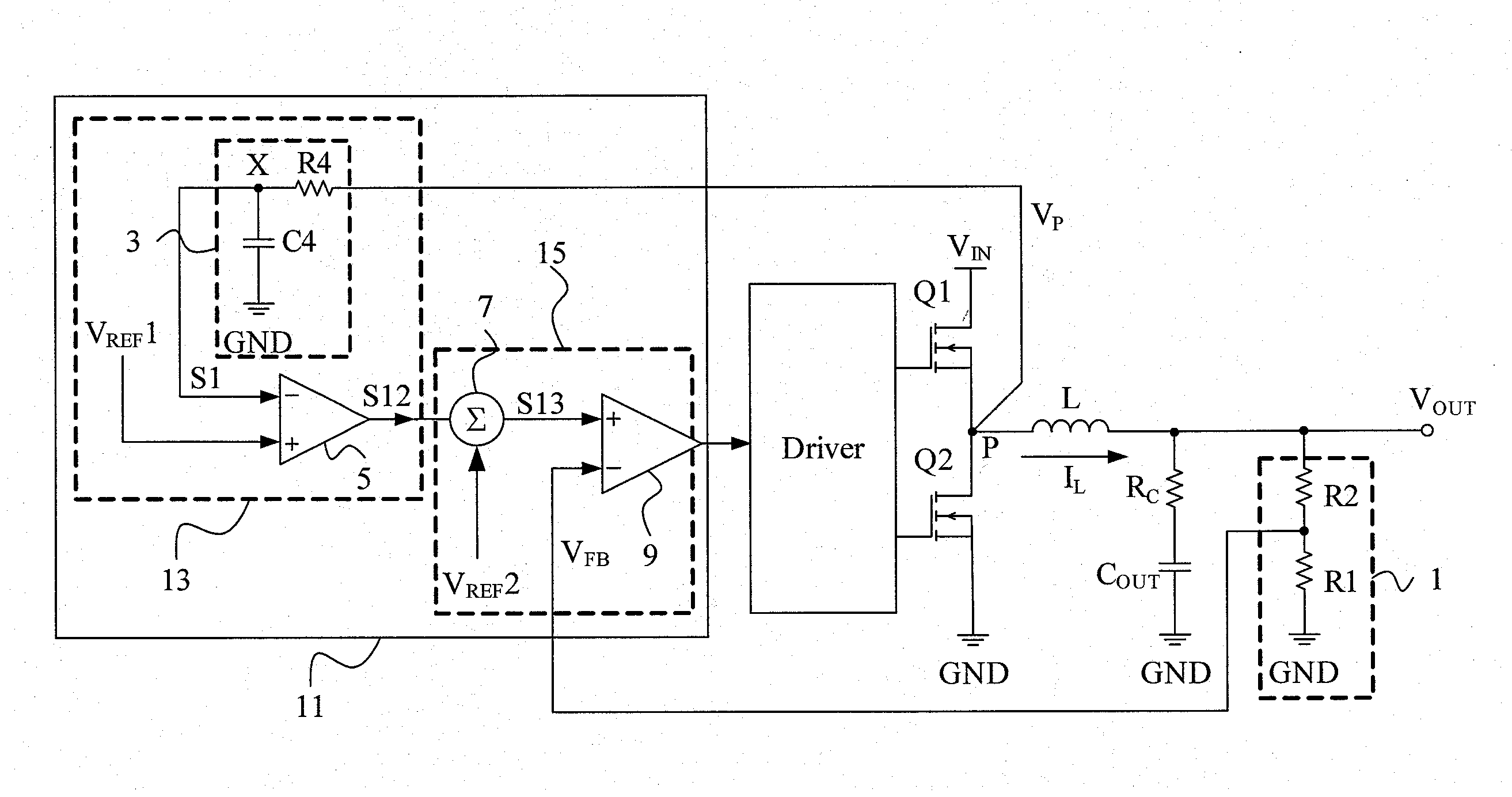
[0023]In a second embodiment as shown in FIG. 4, the MOSFETs Q1 and Q2, the output inductor L, the output capacitor COUT, and the resistor voltage divider 1 are configured as in the circuit of FIG. 3, and the PWM controller 21 also includes a synchronous-signal generator 23 and a PWM comparator circuit 25, but has a slightly different configuration from its counterpart shown in FIG. 3. In the synchronous-signal generator 23, the second signal 51 is also generated by the first low-pass filter 3 by filtering out the high-frequency component of the phase-node voltage VP and thus synchronous and in phase with the inductor current IL and similar to a triangular wave, but is provided for the positive input of the error amplifier 5 whose negative input is the first reference voltage VREF1. Likewise, the error amplifier 5 multiplies the difference between the second signal S1 and the first reference voltage VREF1 by an appropriate multiplication factor to generate a first signal S22 which i...
third embodiment
[0024]The third embodiment shown in FIG. 5 has a same configuration as that of FIG. 3, except that a synchronous-signal generator 33 is slightly different from its counterpart shown in FIG. 3. Likewise, the synchronous-signal generator 33 is in a PWM controller 31 including the PWM comparator circuit 15 and, however, includes a second low-pass filter 30 in addition to the first low-pass filter 3 and the error amplifier 5. The second low-pass filter 30 composed of a resistor R5 and a capacitor C5 filters out most of the AC component of the second signal S1 to generate a first reference voltage VREF1 which is similar to a DC voltage and represents the DC component of the output voltage VOUT. Therefore, the first signal S12 generated by the error amplifier 5 from the difference between the first reference voltage VREF1 and the second signal S1 is proportional to the slope of the inductor current IL and, in an IC package where no pins are provided for feedback of the output voltage VOUT...
fourth embodiment
[0025]The fourth embodiment shown in FIG. 6 has a same configuration as that of FIG. 4, except that a synchronous-signal generator 43 is slightly different from its counterpart shown in FIG. 4. Likewise, the synchronous-signal generator 43 is in a PWM controller 41 including the PWM comparator circuit 25 and, however, includes the second low-pass filter 30 in addition to the first low-pass filter 3 and the error amplifier 5, to filter out most of the AC component of the second signal S1 to generate the first reference voltage VREF1 similar to a DC voltage representing the DC component of the output voltage VOUT. This embodiment has the same advantages as those of the circuit shown in FIG. 5.
PUM
 Abstract
Description
Claims
Application Information
 - R&D
- Intellectual Property
- Life Sciences
- Materials
- Tech Scout
- Unparalleled Data Quality
- Higher Quality Content
- 60% Fewer Hallucinations
Browse by: Latest US Patents, China's latest patents, Technical Efficacy Thesaurus, Application Domain, Technology Topic, Popular Technical Reports.
© 2025 PatSnap. All rights reserved.Legal|Privacy policy|Modern Slavery Act Transparency Statement|Sitemap|About US| Contact US: help@patsnap.com


