Oil pressure regulating valve for generator applications

a technology of oil pressure regulating valve and generator, which is applied in the direction of fluid pressure control, process and machine control, instruments, etc., can solve the problems of affecting the operation of the current pressure regulating valve, the force of the valve in the present pressure regulating valve is not always sufficient to shear debris, and the oil may sometimes be entrained in the oil and block the ports associated with the pressure regulating valv

Active Publication Date: 2010-11-11
HAMILTON SUNDSTRAND CORP
View PDF13 Cites 20 Cited by
  • Summary
  • Abstract
  • Description
  • Claims
  • Application Information

AI Technical Summary

Benefits of technology

[0007]A valve sleeve for use in a pressure regulating valve of a generator includes a valve sleeve having a length, and a flange at one end. A portion of the valve sleeve extends inwardly from the flange to form a ledge extending...

Problems solved by technology

The existing pressure regulating valves in generators have some challenges.
In one challenge, debris may sometimes be entrained in the oil and block the ports associated wit...

Method used


Image

  • Oil pressure regulating valve for generator applications
  • Oil pressure regulating valve for generator applications
  • Oil pressure regulating valve for generator applications

Examples


Embodiment Construction

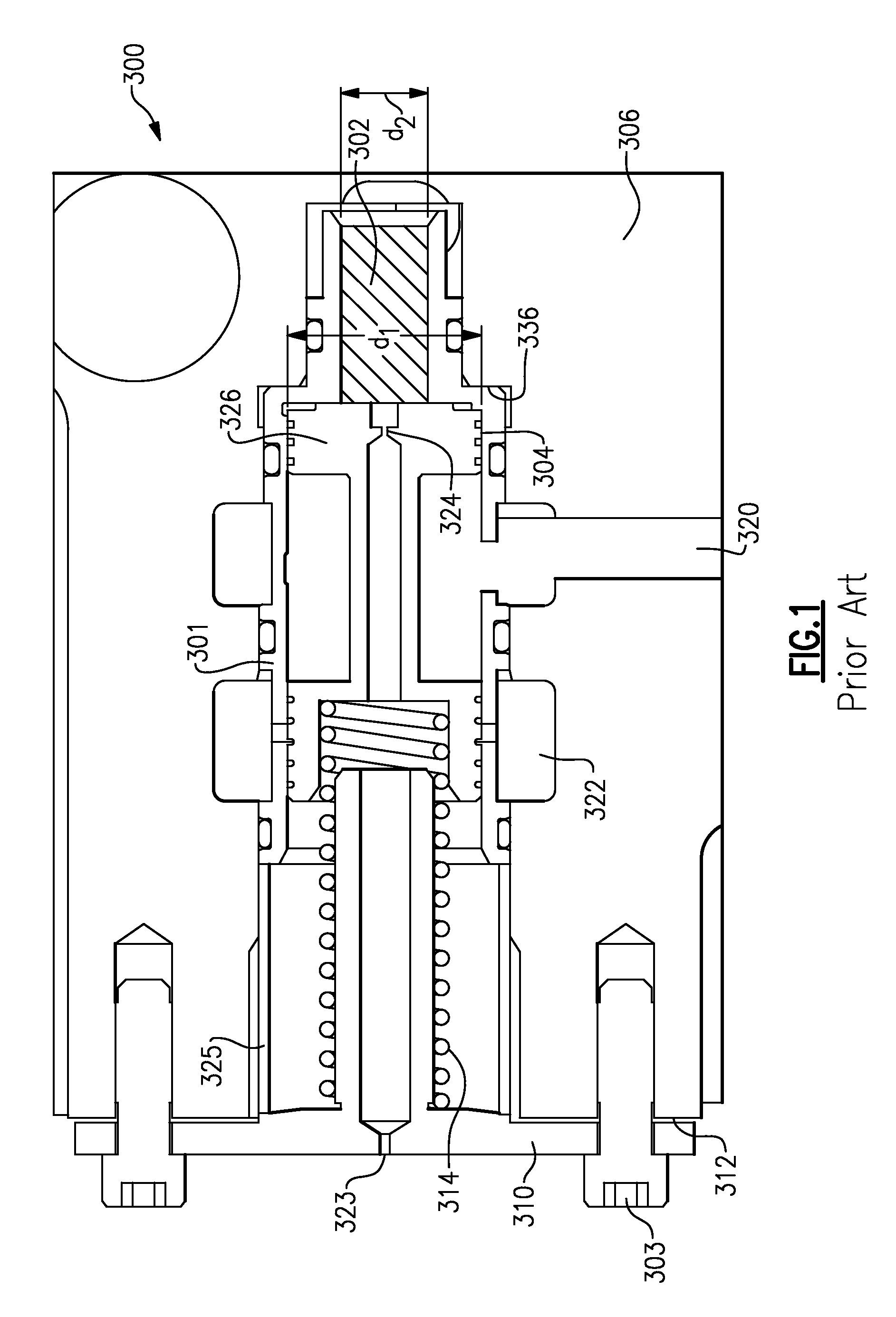
[0016]A prior art valve 300 is illustrated in FIG. 1. In the prior art valve 300, an outer housing 306 receives a valve spool 326. A sense piston 302 is positioned at one side of the valve spool 326, and a spring 314 biases the valve spool 326 toward the sense piston 302. A valve cover 310 is clamped against an outer face 312 of an outer edge of clamp collar 325. The clamp collar 325 is forced to the right as shown in this figure by the cover 310, and against a sleeve 301. The sleeve 301 is forced against an end face 336 of the housing 306, and can be subject to distortion by this contact when bolts 303 are tightened. The valve is carefully designed and engineered, and this distortion can effect the overall efficient operation of the valve system.

[0017]The valve spool 326 moves to the left and right and regulates flow between an inlet port 320 and an outlet port 322. Outlet port 322 leads to various uses for oil in a generator. Bleed orifice 323 is formed at an end of the valve cove...


PUM


Abstract

A generator includes a rotor to be driven to rotate and generate electricity and a housing receiving the rotor. An oil supply includes an oil inlet port and an oil outlet port. A pressure regulating valve regulates the flow of oil from the inlet port to the outlet port. The pressure regulating valve includes a valve sleeve mounted within the housing. The valve sleeve extends into a bore within the housing. A valve spool is mounted within the valve sleeve. The valve sleeve has a flange abutting an outer face of the housing. Bolts tighten the flange against the housing. An inner end of the valve sleeve extends radially inwardly to form a ledge. The ledge is spaced away from an inner face of the housing. A valve sleeve, a sense piston and a valve spool are also disclosed and claimed.

Description

BACKGROUND OF THE INVENTION[0001]This application relates to an oil regulating valve for use in an electrical generator.[0002]Generators are known, and typically include a rotor which is driven to rotate by a source of rotation, such as a gas turbine engine on an aircraft. The rotor carries electric windings, which rotate in proximity to stator windings. The relative rotation of the rotor adjacent to the stator generates electricity.[0003]Generators are also provided with many auxiliary systems and components. Oil is required to be delivered to several locations within the generator to ensure continued efficient operation of the systems and components.[0004]It is known to provide a pressure regulating valve on an oil flow line to control the volume of oil being delivered to downstream uses dependent on the pressure of the oil. The existing pressure regulating valves in generators have some challenges. In one challenge, debris may sometimes be entrained in the oil and block the ports...

Claims


Application Information

Patent Timeline
IPC IPC(8): H02K9/00F16K1/00
CPCG05D16/103G05D16/10G05D16/024Y10T137/7668Y10T137/86791
Inventor LEMMERS, JR., GLENN C.BEHLING, DAVID S.FRANZEN, MARK F.
Owner HAMILTON SUNDSTRAND CORP
Why Eureka
Try Eureka