
Connector

a technology of connecting rods and connectors, applied in the direction of pipe joints, non-disconnectible pipe joints, sleeves/socket joints, etc., can solve the problems of not all pipes are made from materials having suitable properties, not always desirable to put pipes under stress, and more flexible pipes such as garden hoses cannot withstand such squeezing and require different connectors. , to achieve the effect of strong and reliable connection, convenient and convenient use, and simple us

Inactive Publication Date: 2010-11-11
DESIGN TECH & INNOVATION
View PDF15 Cites 3 Cited by
  • Summary
  • Abstract
  • Description
  • Claims
  • Application Information

AI Technical Summary

Benefits of technology

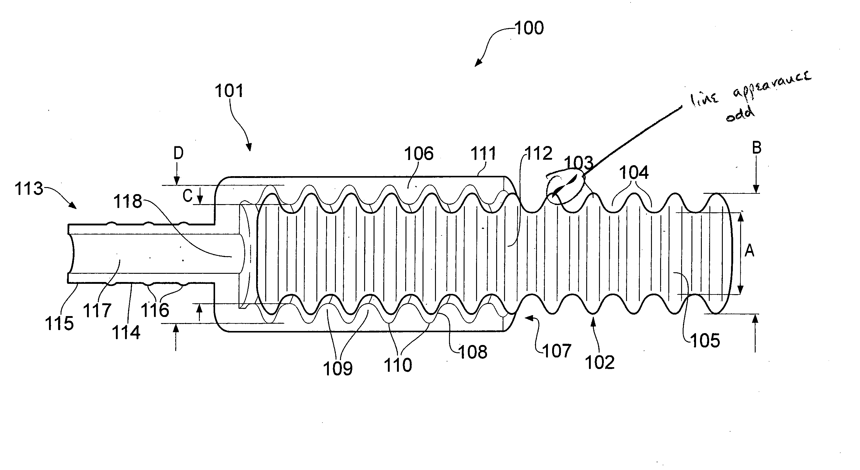
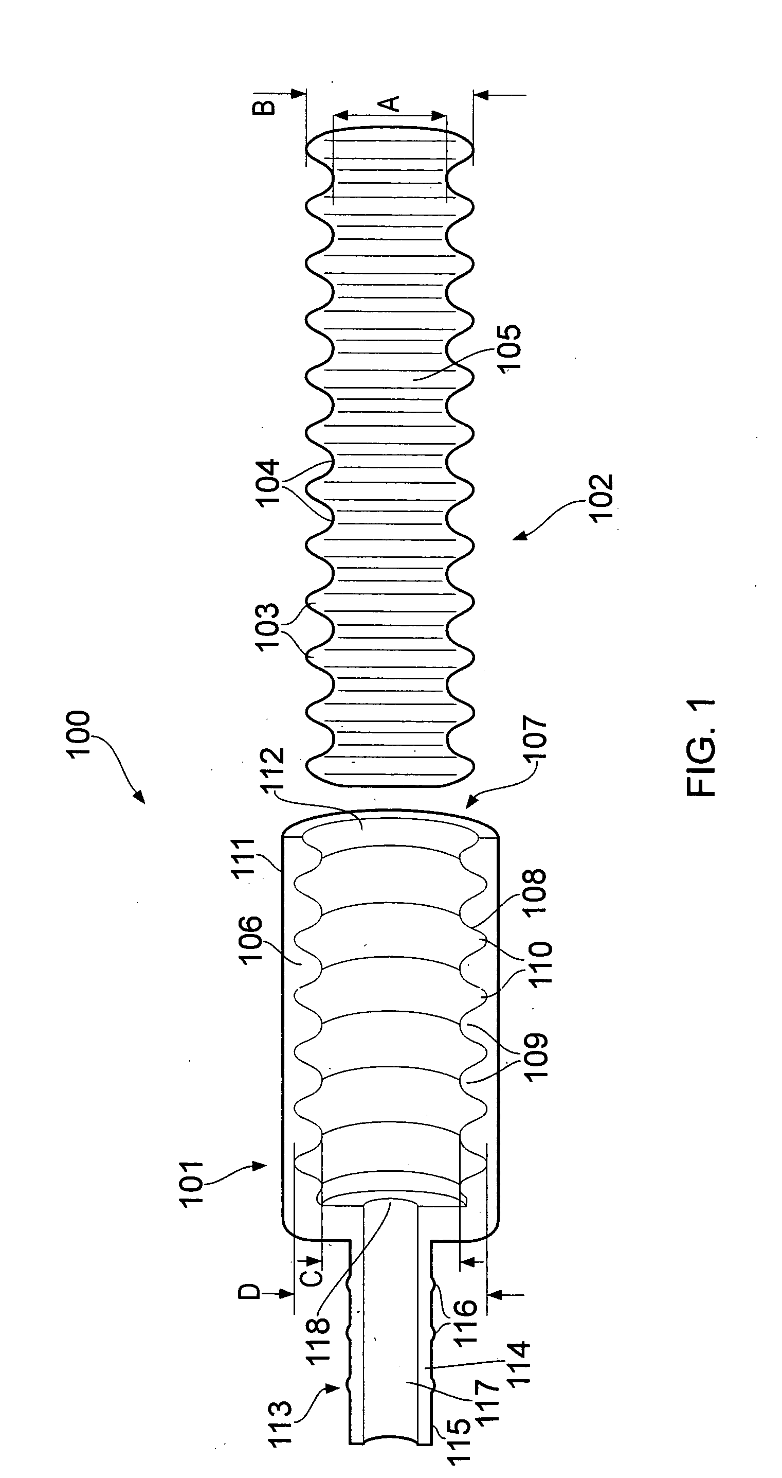
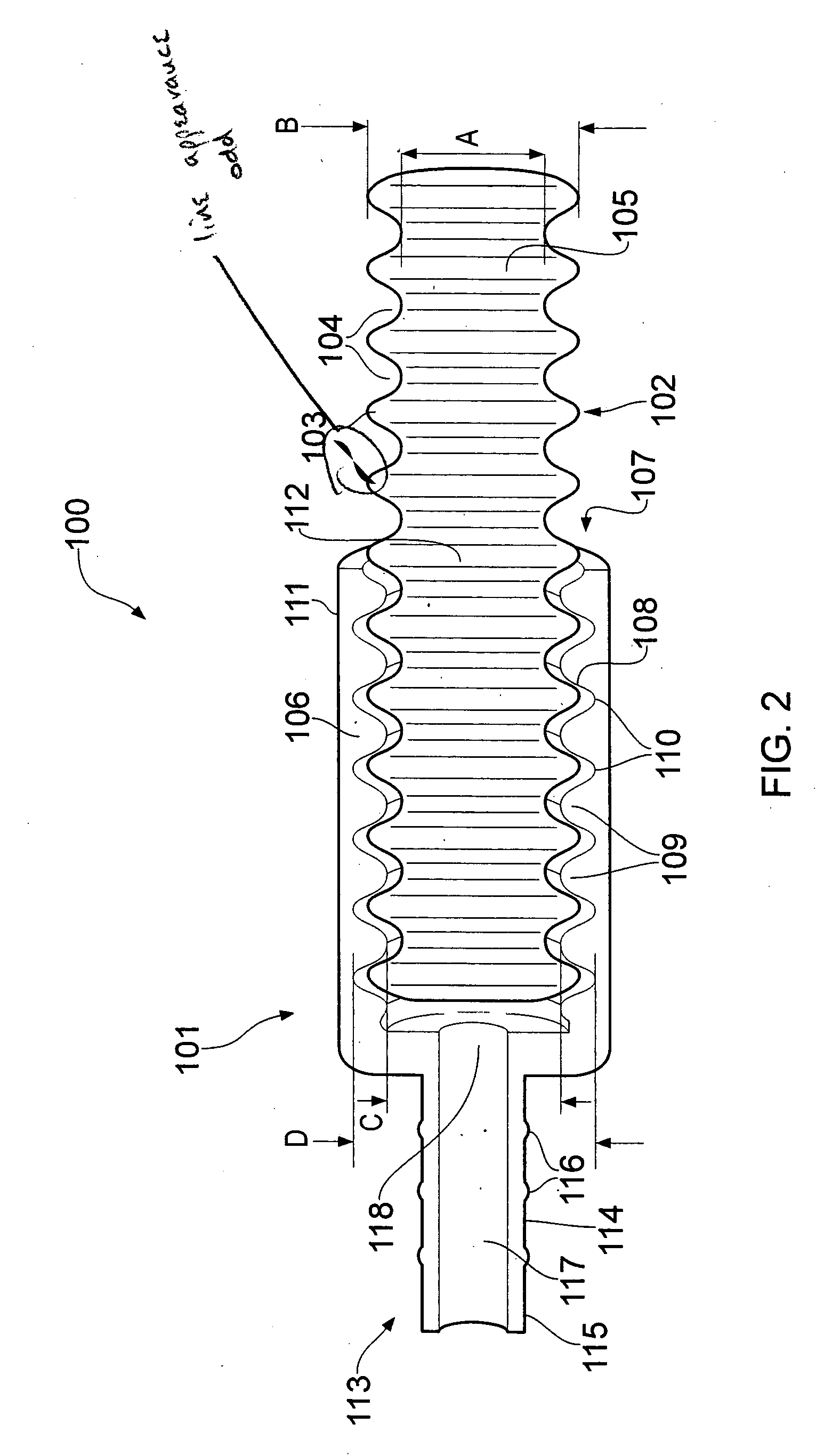
"The present invention provides a connector for a pipe that can expand inside the connector without too much stress being applied to the pipe. This is achieved by a cavity in the connector that can vary in width to hold the pipe snugly and allow it to expand as fluid is added. The connector can be easily fitted to the pipe and is convenient to use. It can be made as a single piece and can be used with a variety of pipes. The inner surface of the cavity can be corrugated to improve the fit of the pipe and create a better seal between the pipe and the connector. The corrugation can be in the form of ridges or grooves and can be threaded or undulate along its length. The depth of the grooves or ridges can vary to control the seal and allow the pipe to expand or contract as needed. Overall, the invention provides a convenient and easy-to-use connector for pipes that can expand and contract without compromising the strength of the connection."

Problems solved by technology

More complex connectors tend to rely on some kind of compression fit.
Of course, connectors that rely primarily on forcing a sleeve against the outside of a pipe are only suitable for stiff pipes that can withstand being squeezed from the outside sufficiently to allow a seal to be formed between the pipe and the sleeve.
More flexible pipes, such as garden hoses, cannot withstand such squeezing and require different connectors.
However, not all pipes are made from materials having suitable properties.
Furthermore, it is not always desirable to put pipes under stress by compressing them, as this can degrade the material from which they are made and weaken the pipe.
Certain types of pipe may also inherently shrink and expand under environmental conditions.
In particular, if a compression type connector is fitted to a pipe that subsequently expands, the stress the connector applies to the pipe will increase, which may lead to the seal between the connector and pipe breaking or the pipe distorting.
These connectors also tend to have multiple components, which can make them prone to break or wear out and adds to manufacturing complexity.

Method used


Image

  • Connector
  • Connector
  • Connector

Examples


first embodiment

[0039]Referring to FIG. 3, a connection system 300 according to a second preferred embodiment of the present invention is similar to the connection system 100 according to the first preferred embodiment of the invention and the same reference numerals are used for similar components. In particular, it can be seen that the connection system 300 according to the second preferred embodiment has a connector 101 identical to that of the first preferred embodiment. However, in the second preferred embodiment, the connector 101 connects to a pipe 302 that has a smooth outer surface 303, e.g. having a constant diameter E in its dehydrated state. The diameter E of the outer surface 303 of the pipe 302 in its dehydrated state is approximately the same as the maximum diameter B of the pipe 102 of the In other words, the maximum diameter D of the cavity 107 of the connector 101 is greater than the diameter E of the pipe 302 and the minimum diameter C of the cavity 107 is less than the diameter...

third embodiment

[0040]Referring to FIG. 4, a connection system 400 according to a third preferred embodiment of the present invention is similar to the connection system 100 of the first preferred embodiment of the invention and the same reference numerals are used for similar components. However, in the third embodiment, the cavity 107 of a modified connector 401 has an inner surface 402 corrugated with grooves 403 that have a widening towards their base. This means that the pair of ridges 404 on either side of each groove 403 form a narrowing or neck 405 toward the opening of each ridge 404. As the pipe 102 expands on hydration, its ridges 103 expand into the grooves 403 of the connector 401. In particular, they expand into the widened part of the grooves 403. This has the effect of locking the ridges 103 of the pipe 102 in the grooves 403 of the connector 301, strengthening the connection between pipe 102 and connector 401.

[0041]The connector 101 of the first embodiment can be also be modified i...


PUM

PropertyMeasurementUnit
outer widthaaaaaaaaaa
widthaaaaaaaaaa

Abstract

A connection system comprises a connector and a pipe. The pipe is made from a hydrophilic membrane capable of pervaporating brackish water or such like as substantially pure water, such as Dutyion™. One feature of this material is that it expands significantly as it hydrates. The pipe is generally cylindrical, but it is corrugated along its length, with roughly regular ridges and grooves. The connector has a side wall defining a substantially cylindrical cavity. The inside surface of the cavity is corrugated in the similar way to the pipe. When the pipe is in a dehydrated state, the cavity of the connector has a maximum diameter D greater than the maximum diameter B of the pipe and a minimum diameter C less than the maximum diameter B of the pipe. The pipe can be inserted in the cavity of the connector in a dehydrated state. When the system then carries water, the pipe hydrates, which causes the pipe to expand and its diameter to increase. This means that the ridges of the pipe expand into the grooves of the cavity and the pipe fits more tightly into the cavity and the seal between the pipe and the cavity is improved.

Description

FIELD OF THE INVENTION[0001]This invention relates to a connector for connection to a pipe. It also relates to a connection system comprising a connector and pipe and to a method of connection using the same. A particular application of the invention is a connector for connection to a pipe made from an expandable material that expands into a cavity of the connector in use.BACKGROUND TO THE INVENTION[0002]Perhaps the simplest form of pipe connector is a sleeve for connecting two pipes together. The sleeve may fit around an end of each pipe and be sealed in position to effectively make the two pipes one. This is often seen in domestic plumbing, where the sleeve is usually made from copper and soldered onto copper pipes.[0003]More complex connectors tend to rely on some kind of compression fit. For example, a sleeve may be fitted onto the end of a pipe that squeezes around the outside of the pipe to form a seal. Often, a sealing component, such as an o-ring seal or an olive, is provide...

Claims


Application Information

Patent Timeline
Patent Type & Authority Applications(United States)
IPC IPC(8): F16L25/10
CPCF16L13/00F16L47/24F16L47/20F16L25/0036
Inventor TONKIN, MARK CHRISTOPHERWATSON, REBECCA
Owner DESIGN TECH & INNOVATION
Learn More