
Antenna pointing bias estimation using radar imaging

a radar imaging and antenna pointing technology, applied in direction controllers, using reradiation, instruments, etc., can solve the problems of large errors in the apparent direction of the scene being imaged, anechoic chambers that are expensive to build and maintain, and approaches that are typically expensive and/or burdensome, so as to minimize the sum of squares of doppler errors and minimize the effect of doppler errors

Active Publication Date: 2010-11-11
RAYTHEON CO
View PDF14 Cites 9 Cited by
  • Summary
  • Abstract
  • Description
  • Claims
  • Application Information

AI Technical Summary

Benefits of technology

[0008]The need in the art is addressed by the system and method for estimating an antenna boresight direction of the present invention. The novel system includes a first circuit for receiving a Doppler measurement and a line-of-sight direction measurement corresponding with the Doppler measurement, and a processor adapted to search for an estimated boresight direction that minimizes a Doppler error between the Doppler measurement and a calculated Doppler calculated from the estimated boresight direction and the line-of-sight direction measurement. The li

Problems solved by technology

These biases can lead to large errors in the apparent direction of the scene being imaged and, consequently, in the target location.
Factory alignment and on-aircraft target calibration can reduce gimbal biases, but these approaches are typically expensive and / or burdensome.
Factory electrical alignment requires anechoic chambers that are expensive to build and maintain, since they themselves need calibration.
Aircraft calibration targets also add to the cost of the aircraft, and raise maintenance costs.
Neither of these options really simulates a target in the far field environment because of the limited space within which they are required to operate.
Also, vibration from transportation or aircraft environments can introduce additional mechanical biases after the total initial biases, both electrical and mechanical, have been removed through calibration.

Method used


Image

  • Antenna pointing bias estimation using radar imaging
  • Antenna pointing bias estimation using radar imaging
  • Antenna pointing bias estimation using radar imaging

Examples


Embodiment Construction

[0014]Illustrative embodiments and exemplary applications will now be described with reference to the accompanying drawings to disclose the advantageous teachings of the present invention.

[0015]While the present invention is described herein with reference to illustrative embodiments for particular applications, it should be understood that the invention is not limited thereto. Those having ordinary skill in the art and access to the teachings provided herein will recognize additional modifications, applications, and embodiments within the scope thereof and additional fields in which the present invention would be of significant utility.

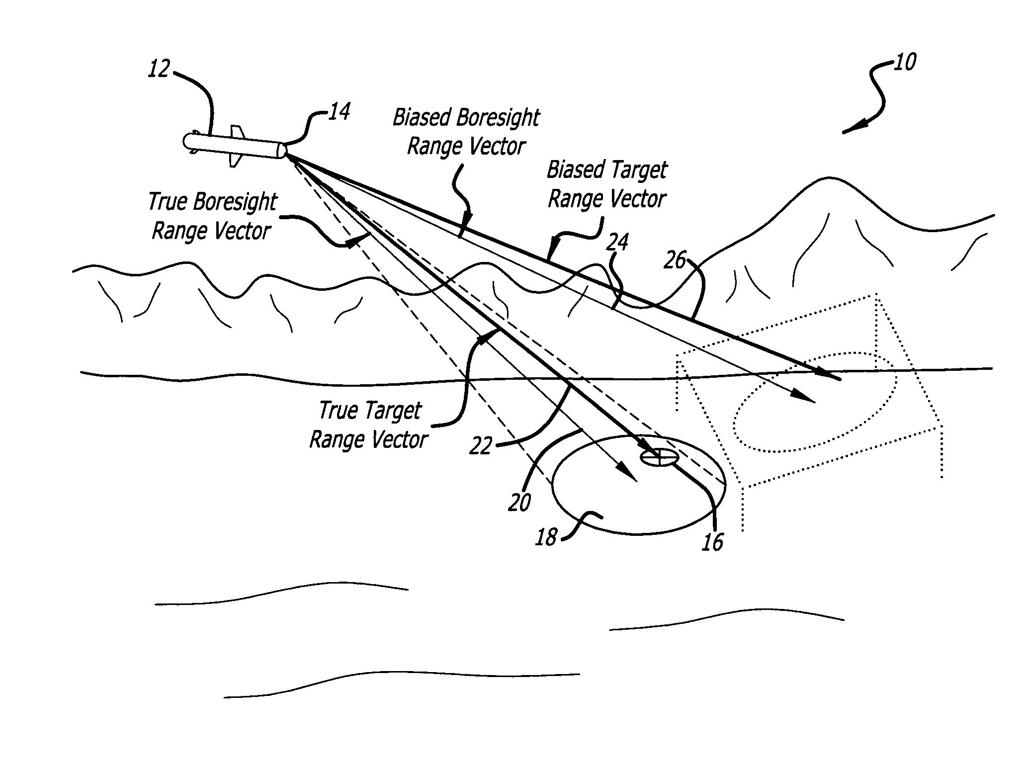
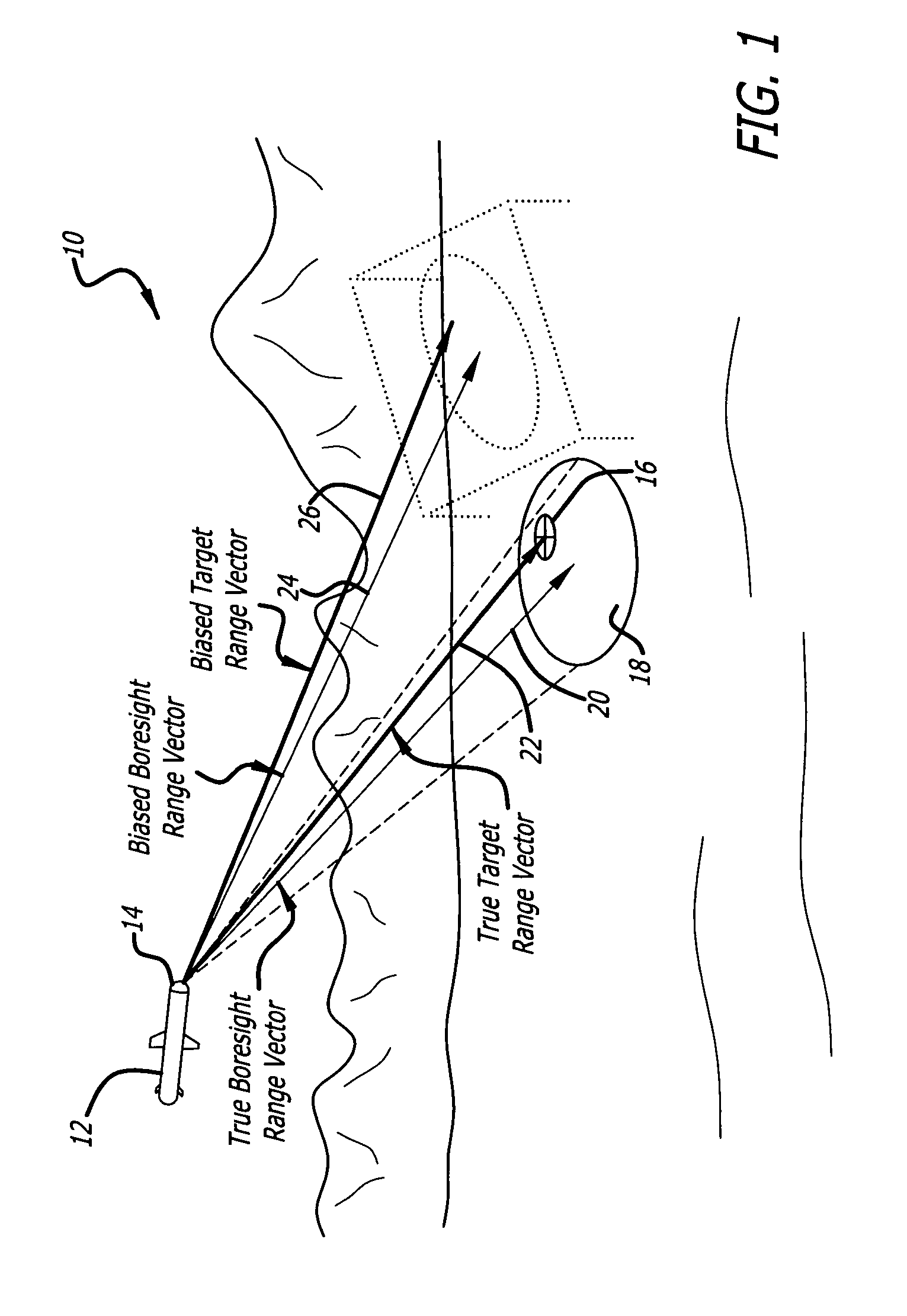
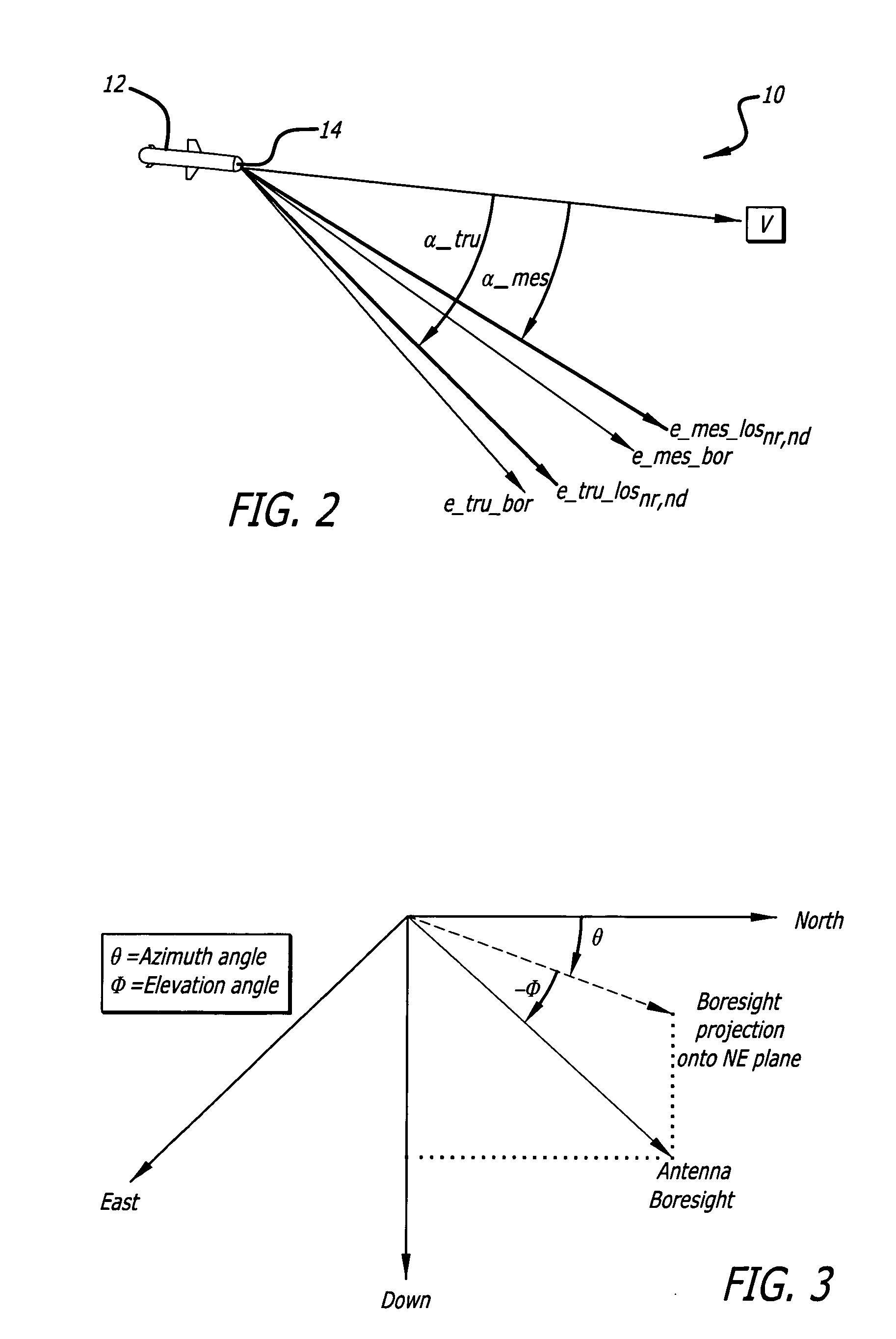
[0016]FIG. 1 is a simplified diagram of an illustrative scenario 10 showing the problem addressed by the present invention. A missile 12 is equipped with an imaging radar seeker 14 that uses radar measurements to guide the missile 12 toward a target 16. The imaging radar, which may be, for example, a synthetic aperture radar (SAR) or Doppler beam sha...


PUM


Abstract

A system for estimating an antenna boresight direction. The novel system includes a first circuit for receiving a Doppler measurement and a line-of-sight direction measurement corresponding with the Doppler measurement, and a processor adapted to search for an estimated boresight direction that minimizes a Doppler error between the Doppler measurement and a calculated Doppler calculated from the estimated boresight direction and the line-of-sight direction measurement. The line-of-sight direction measurement is measured relative to the true antenna boresight, and the calculated Doppler is the Doppler calculated for a direction found by applying the line-of-sight direction measurement to the estimated boresight direction. In a preferred embodiment, the first circuit receives a Doppler measurement and a line-of-sight direction measurement from each of a plurality of pixels, and the processor searches for an estimated boresight direction that minimizes a sum of squares of Doppler errors for each of the pixels.

Description

BACKGROUND OF THE INVENTION[0001]1. Field of the Invention[0002]The present invention relates to radar systems. More specifically, the present invention relates to systems and methods for correcting for antenna gimbal biases.[0003]2. Description of the Related Art[0004]Guiding a missile to a target requires an accurate measurement of the target's three-dimensional location relative to the missile. Precise target location to the degree required for weapon midcourse / terminal engagement is well known for air targets but less so for ground targets where the engagement is typically based on radar seekers and imaging technology.[0005]An imaging radar can determine the location of a ground target with the assistance of monopulse measurements that estimate the direction of each pixel in the radar image relative to the antenna boresight. An imaging radar system typically includes a radar antenna having a pointing mechanism, such as a gimbal or electronically scanned pointing, for controlling...

Claims


Application Information

Patent Timeline
IPC IPC(8): F42B15/01G01S13/44G01S13/90H01Q3/00
CPCH01Q1/125H01Q1/18H01Q1/28F41G7/2286F41G7/001F41G7/2213F41G7/2246H01Q3/08
Inventor GUERTIN, RALPHFAULKNER, DAVIDTREECE, JOHNBRUYERE, DONALD
Owner RAYTHEON CO
Learn More