
Gas block and installation device

a technology of gas block and installation device, which is applied in the direction of weapons, butts, manufacturing tools, etc., can solve the problems of reducing firearm handling qualities and adding to firearm bulk, and achieve the effect of reducing overall firearm bulk and improving firearm handling qualities

Inactive Publication Date: 2010-11-11
TANKERSLEY JEROME BENEDICT
View PDF6 Cites 35 Cited by
  • Summary
  • Abstract
  • Description
  • Claims
  • Application Information

AI Technical Summary

Benefits of technology

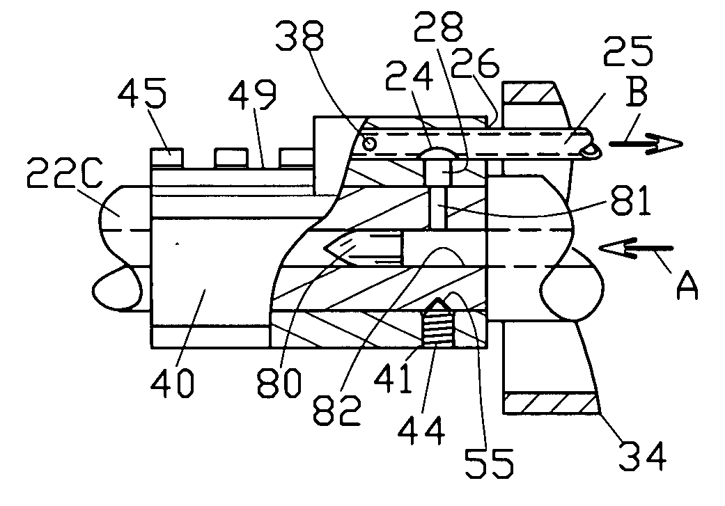
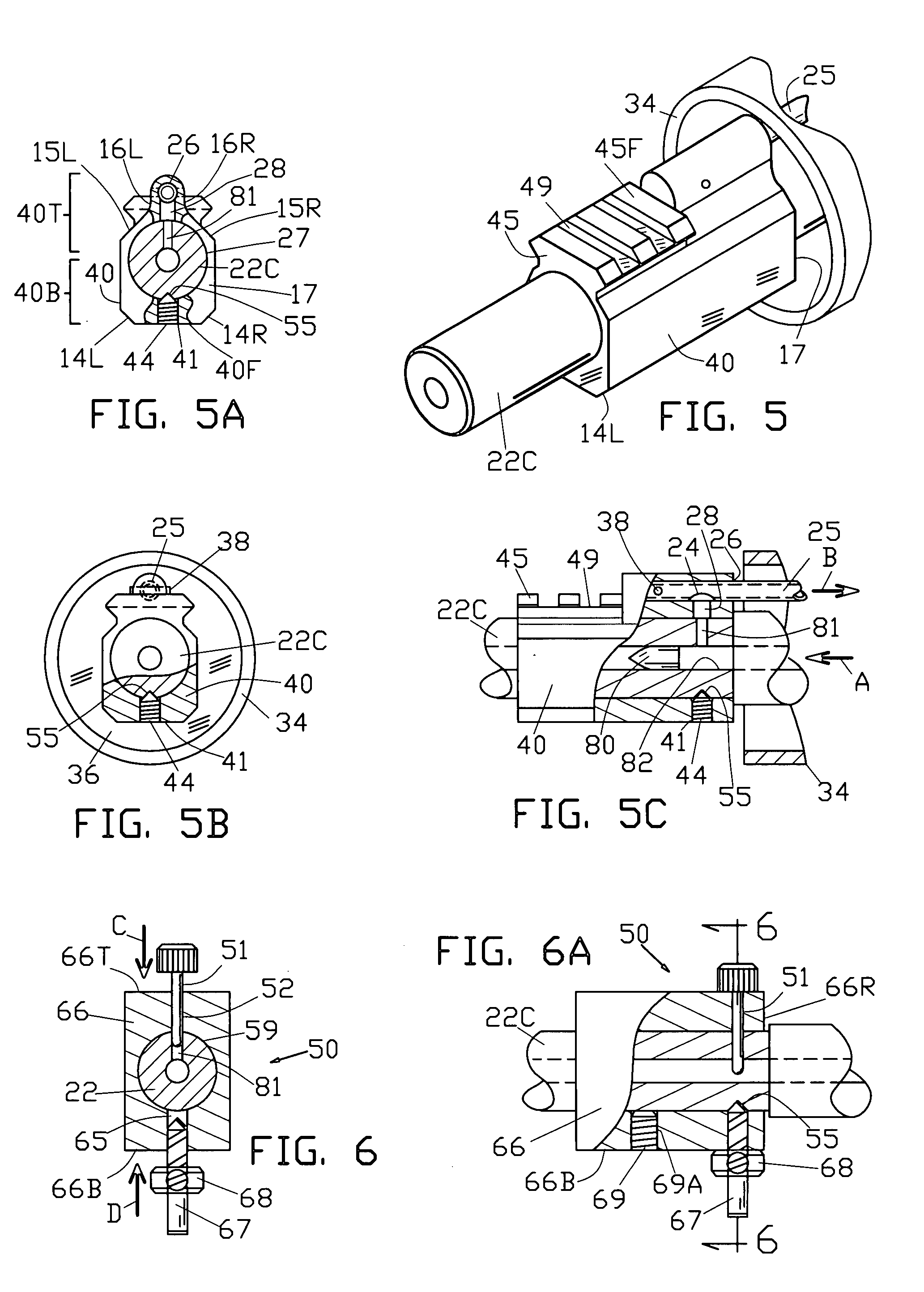
[0012]Provided is an improved gas block and installation device for a firearm. The improved gas block permits cartridge combustion gas to flow from a firearm barrel to a firearm gas tube or operating element, and may include an integral rail located forward of the gas tube, the rail located close to the barrel surface, instead of outboard the gas tube as seen in the prior art. This unique feature allows devices to be attached closer to the barrel, thus improving firearm handling qualities, reducing overall firearm bulk, and allowing a firearm handguard to pass over the gas block during maintenance, thus eliminating the need for gas block removal.
[0013]A second unique feature of this invention is that the means for securing the improved block to the barrel may include a conical point set screw in the improved gas block engaging a conical cavity in the firearm barrel, providing self alignment and clamping, with one part, at factory and thereafter.
[0014]An installation device is provided for accurately forming the barrel conical cavity diametrically opposite the barrel gas port for mating and aligning with a gas block cone point set screw.DRAWINGS—FIGURES

Problems solved by technology

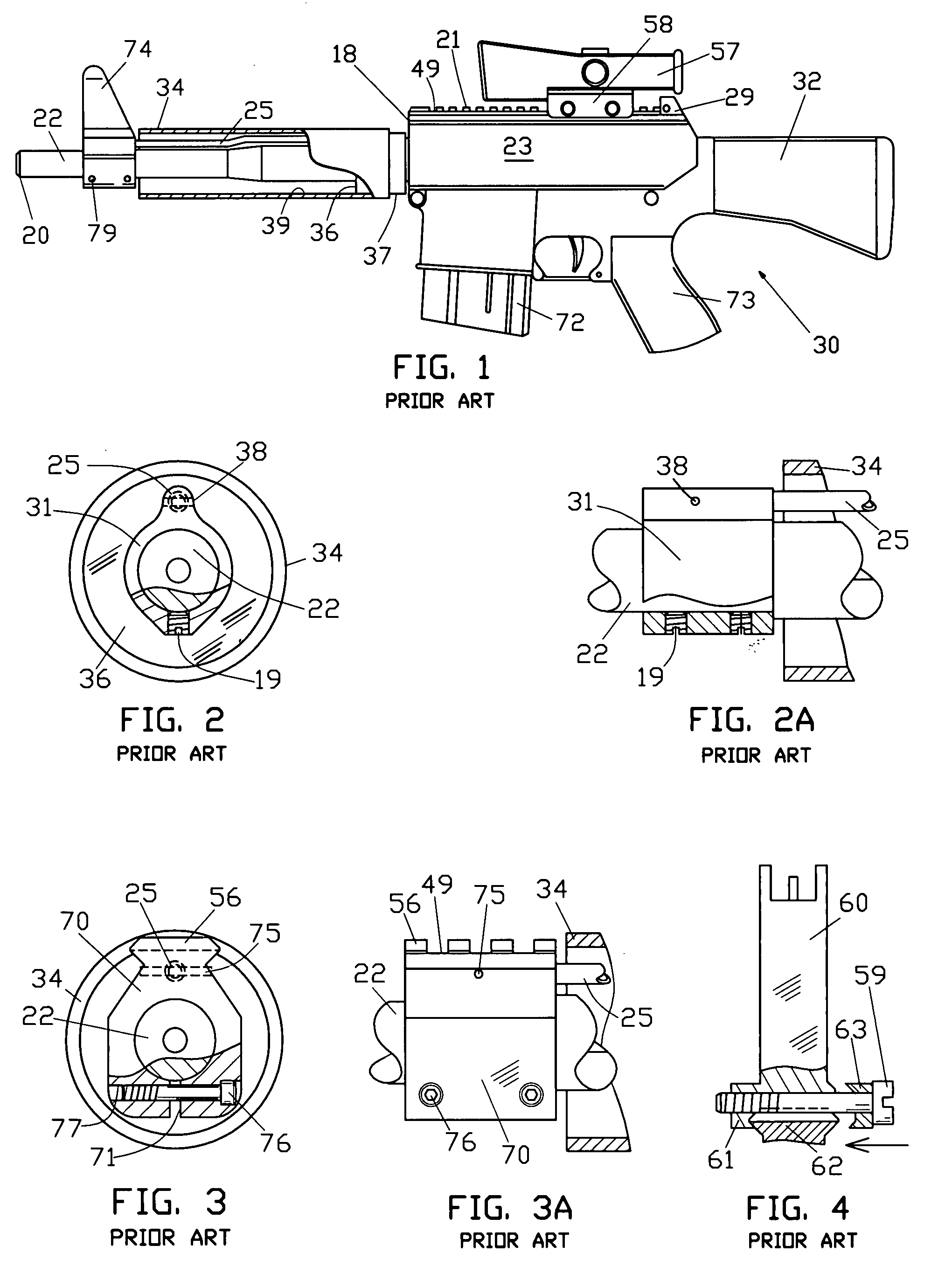
(a) As a group, after initial factory installation, prior art gas blocks can be characterized as difficult to remove and reinstall while maintaining alignment to the firearm gas port. At initial manufacture, the blocks are generally aligned with the barrel port by means of special fixtures. Consequently, when the gas blocks are removed for any reason, skilled armorers and / or fixtures, or a trial and error method must be used to ensure proper alignment at installation. Robbins, U.S. Pat. No. 5,945,626 includes a key, separate from the securing means, thus requiring two parts to accomplish aligning and securing the gas block, unlike the present invention.
(b) Free-float tubular handguard tubes are becoming the standard for many M16 style firearms. With the exception of some low profile gas blocks, prior art gas blocks must be removed from the firearm prior to installation or removal of the handguard.
(c) Prior art integral rail gas blocks are configured to attach ancillary devices substantially outboard of the barrel, the gas block rail being located radially outward of the gas tube, thereby reducing firearm handling qualities and adding to firearm bulk.

Method used


Image

  • Gas block and installation device
  • Gas block and installation device
  • Gas block and installation device

Examples


third embodiment

[0164]Shown is a third embodiment gas block 43 attached to barrel 22C, a block top portion 43T, and a bottom portion 43B with a bottom outward face 43F, a top rail 64, a bayonet lug 33, a longitudinal slot 48, and a clamp screw 46, one of a plurality. A block threaded aperture 54, one of a plurality, receives clamp screw 46.

[0165]FIG. 9A is a side elevational view of the block of FIG. 9, with partial sections. Shown are gas block 43, attached to barrel 22C, top rail 64, bayonet lug 33, tube 25, a transverse slot 35, plurality of screws 46, and cone point screw 44 engaging threaded aperture 41, and mating with barrel conical cavity 55.

[0166]Referring to FIGS. 9-9A together, bayonet lug 33 is disposed on block top portion 43T, forward of top rail 64. Lug 33 is adapted for attaching a standard bayonet or other device with a compatible mounting means, not shown.

embodiment 40

[0167]Improved block 43 is similar to block embodiment 40 in that it includes similar top rail 64 and cone point set 44 engaging threaded aperture 41. Block 43 differs from embodiment block 40 by including lug 33 and also including the plurality of clamp screws 46, the clamp screws 46 disposed at transverse threaded apertures 54 in the block bottom portion 43B, forward of set screw 44.

[0168]The block lower portion 43B includes transverse slot 35 through the block, the slot 35 is disposed forward of set screw 44 for separating the clamp screw clamping action from the set screw clamping action, the transverse slot 35 height dimension lying in a vertical plane. Block lower portion longitudinal slot 48 is centrally located, and slot 48 intersects with the block transverse slot 35 and extends forward through the block, the slot 48 breaking into the block first longitudinal bore 27 and through the block bottom outward face 43F, the slot permitting transverse clamping of the block 43 to th...


PUM

PropertyMeasurementUnit
Pressureaaaaaaaaaa
Widthaaaaaaaaaa
Heightaaaaaaaaaa

Abstract

An improved gas block for a firearm has a first longitudinal bore for receiving a firearm barrel, the barrel having a gas port, the gas block having a second longitudinal bore for receiving a gas tube or operating element. The block includes a vertical bore aligned with the barrel gas port and connecting the first and second block bores and permitting passage of cartridge gas from the barrel gas port to the gas tube. The improved gas block may include a military rail, forward of the gas tube, the forward location permitting the rail and accessories to lie close to the barrel, improving handling and reducing bulk. The barrel may include a conical cavity generally opposite the gas port. The block may include a conical point set screw adapted to mate with the barrel conical cavity, the screw when tightened forcing alignment of the block vertical bore with the barrel gas port and simultaneously clamping the block to the barrel. An installation device provides a means for forming a conical cavity in the barrel surface.

Description

CROSS-REFERENCE TO RELATED APPLICATIONS[0001]NoneFEDERALLY SPONSORED RESEARCH [0002]NoneSEQUENCE LISTING [0003]NoneFIELD OF THE INVENTION[0004]This invention relates to gas blocks for gas operated firearms, and more particularly to gas blocks for M16 style firearms.BACKGROUND OF THE INVENTION—PRIOR ART[0005]Many gas block configurations have been produced during the continuing development cycle for M16 style firearms. While sharing an internal configuration intended for the primary function of conducting combustion gas from the firearm barrel gas port to a gas tube or operating element, prior art blocks differ externally. Gas block external configuration varies substantially depending on the intended block secondary functions.[0006]Gas blocks in general can be categorized, however, as three basic styles: integral front sight, integral rail, and low profile. Prior art gas blocks are attached to the firearm barrel by various means, including pins, clamping, set screws or a combination...

Claims


Application Information

Patent Timeline
IPC IPC(8): F41A5/18F41C27/00F41C27/18B23P11/00
CPCF41A5/26F41C23/16Y10T29/49963F41G11/003F41G1/387
Inventor TANKERSLEY, JEROME BENEDICT
Owner TANKERSLEY JEROME BENEDICT
Learn More